22
5�2
Connection area
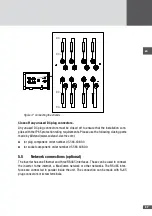
All terminals and cable glands of the inverter are shown in Figure 12.
1
2
3
4
5
7
6
9
10
8
Figure 12 Connection area
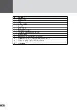
No�
Description
1
DC terminals (MC4 compatible plug-in terminals)
2
"COMM" multiple cable gland for communication cables (network connections, status
signaling contacts, external shutdown)
3
"AC mains" cable gland for the AC input conductor
4
M5 threaded "PE" bolt for the connection of the second protective conductor (optional)
5
AC terminals (screw terminals)
6
External shutdown (plug-in terminal)
7
Status signaling contacts (plug-in terminal)
8
RS485 (plug-in terminal)
9
Ethernet and RS485 communication sockets (RJ45)
10
Cable grips for restraining the cable (for the communication cables)
Summary of Contents for SM30HT4
Page 1: ...Instruction manual SolarMax HT series 30HT4 32HT4...
Page 10: ...10 3 4 Dimensions mm 590 580 397 847 871 Figure 1 Dimensions with wall mounting bracket...
Page 11: ...en 11 3 5 Views of the unit 2 3 4 12 11 9 10 8 7 7 6 1 5 Figure 2 Views of the unit...
Page 74: ...SolarMax Service Center hotline solarmax com www solarmax com service 2014 05 en...

