en
31
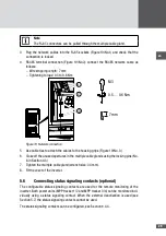
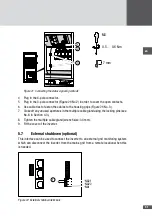
0.5 … 0.6 Nm
M3
7 mm
1
2
3
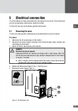
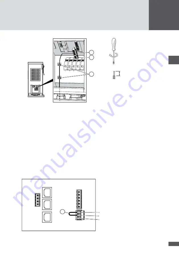
Figure 21 Connecting the status signaling contacts
4. Plug in the 6-pole connector.
5. Plug in the 3-pole connector (Figure 21/No.2) in order to cover the open contacts.
6. Use cable ties to fasten the cables to the housing grips (Figure 21/No. 3).
7. Close off any unused apertures in the multiple cable gland using the locking pins (see
No. 8 in Section 4.3).
8. Tighten the multiple cable gland (wrench size: 34 mm).
9. Fit the cover of the inverter.
5�7
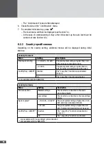
External shutdown (optional)
This interface can be used to connect the inverter to an external grid monitoring system
which can disconnect the inverter from the mains grid from a remote location when this
is needed.
NA21
NA22
NA1
1
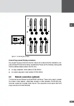
Figure 22 External shutdown terminals
Summary of Contents for SM30HT4
Page 1: ...Instruction manual SolarMax HT series 30HT4 32HT4...
Page 10: ...10 3 4 Dimensions mm 590 580 397 847 871 Figure 1 Dimensions with wall mounting bracket...
Page 11: ...en 11 3 5 Views of the unit 2 3 4 12 11 9 10 8 7 7 6 1 5 Figure 2 Views of the unit...
Page 74: ...SolarMax Service Center hotline solarmax com www solarmax com service 2014 05 en...

