25
en
5 Electrical connection
5.1
Guidelines for electrical installation
DANGER
■
■
Only qualified electricians may install and start-up the TS-SV inverter and the
MCU.
■
■
The local regulations and guidelines for the installation of electrical devices must
be followed.
■
■
All the feed lines to the inverter and the MCU must be appropriate for the expected
voltages, currents and ambient conditions (temperature, UV load, etc.).
■
■
Make sure that all lines are laid tension-free.
5.2 Earthing of the station components
As a principle, all metal parts which are not protected against being touched must be
earthed.
DANGER
A correct earthing is vital for the operation and safety of the devices (for example, by
an earthing strap buried in the ground).
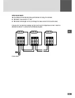
The station components must be earthed as follows:
■
■
Each inverter with two 95 mm
2
wires connected to M10 threaded bolts. The position
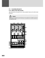
of the MS threaded bolts: see 5.3.1 “Interior view of the inverter”.
■
■
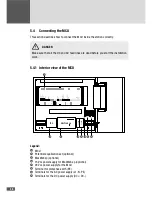
The MCU with one 10 mm
2
wire (also important for perfect communication between
the MCU and inverters). The position of the terminals: see 5.4.1 “Interior view of the
MCU”. The MCU must be grounded independently of the inverters.
■
■
Each of the DC fuse boxes with one 95 mm
2
wire per box.
■
■
The star point of the 400 V coil of the autonomous power supply transformer.
■
■
The AC-side overvoltage protection of the inverter is earthed.
DANGER
Never ground the possibly existing low-voltage star point at the medium-voltage
transformer!
Summary of Contents for TS-SV
Page 1: ...Installation manual SolarMax TS SV 330TS SV 360TS SV...
Page 3: ......
Page 45: ...45 en...
Page 47: ...47 en...

