27
en
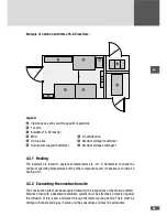
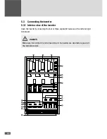
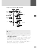
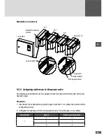
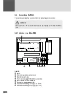
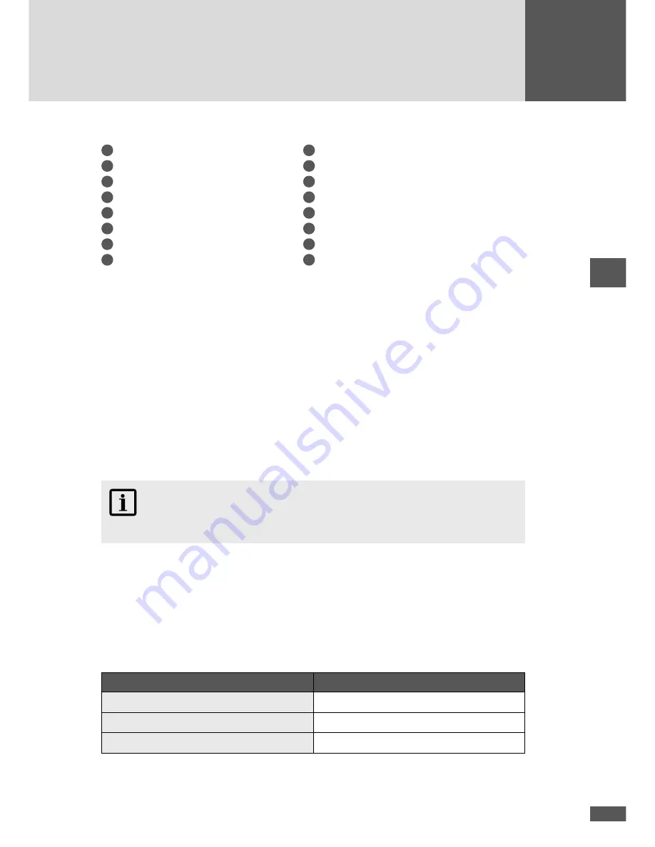
Legend:
1
Power unit PU1
9
DC power switch Q4
2
Power unit PU2
10
DC power switch Q5
3
Power unit PU3
11
DC power switch Q6
4
AC power switch Q1
12
DC connections
5
AC power switch Q2
13
Fuse holder (DC connection for MCU)
6
AC power switch Q3
14
Shutdown contact 1
7
AC connections
15
Fans
8
2 x M10 threaded bolts for earthing
16
Test contacts
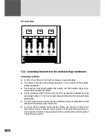
5.3.2 Connecting the inverters to the PV plant
General connection conditions
■
■
Per power unit as many as three DC feed lines (strings) can be connect in parallel.
■
■
Maximum DC input current per power inverter: 720 A
■
■
Maximum DC input voltage per inverter: 900 V
■
■
Maximum DC input current per power unit: 240 A
■
■
If the feed lines are long we recommend you use larger line cross sections to keep
down transmission losses.
■
■
Maximum admissible over-dimensioning of the PV generator output power: 50 %.
NOTE
The DC inputs of the inverter are overvoltage protective Type 3.
Connection conditions for the multi MPPT operating mode
■
■
It is not permitted to install a ground connection to the PV generator.
■
■
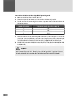
Starting from three DC feed lines for each power unit, the minimum cross section
increases because in case of a short circuit the two intact feed lines pass on all the
return current to the defective line (the cross section increase for three DC feed lines
can be dropped if all the DC feed lines are fitted with fuses):
Number of feed lines per power unit
Minimum cable cross section
1
95 mm
2
2
50 mm
2
3
70 mm
2
Summary of Contents for TS-SV
Page 1: ...Installation manual SolarMax TS SV 330TS SV 360TS SV...
Page 3: ......
Page 45: ...45 en...
Page 47: ...47 en...

