


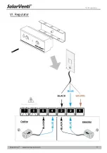

VII. Further installation tips
SolarVenti
®
www.solarventi.com
19
UK
INTRO
TOOLS
p.
6,
14,
15
p.
10
p.
13
p.
15
Installation
manual
for
mounting
SV
standard
to
the
wall
Additional
installation
tips
Optimal
airflow:
In
a
leaky
building
there
is
no
need
for
an
exhaust/pressure
valve.
However,
a
valve
for
air
outlet
should
be
installed
in
a
very
tight
building.
As
far
as
possible
inject
the
air
into
the
driest
room
and
extract
from
the
most
humid
room
to
eliminate
the
risk
of
leading
the
moisture
through
the
rest
of
the
building.
The
hole
:
Drilling
through
a
wall
can
be
challenging
and
the
tools
needed
to
make
the
hole
will
depend
on
the
material
of
the
wall.
Contact
your
local
SolarVenti
installer
for
further
advice
regarding
the
drilling
and
the
installation.
Take
care
not
to
drill
into
cables,
power
sockets,
etc.
The
optimal
diameter
of
the
hole
is
Ø133
mm
on
the
inside
and
Ø140
mm
on
the
outside.
However,
it
is
possible
to
use
a
diameter
of
Ø135
mm
both
inside
and
outside.
Cable:
The
cable
of
the
Solar
Air
Collector
may
either
go
through
the
hole
of
the
air
inlet
–
as
shown
above
–
or
a
separate
6
‐
8
mm
hole
may
be
drilled
in
the
position
desired.
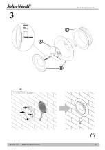
Stands:
Drill
two
holes
in
each
rack
and
mount
them
to
the
wall
with
suitable
screws.
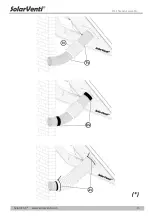
The
plastic
strips
(Jv)
are
to
be
tightened
around
the
flexible
hose
(Iv)
approximately
in
the
middle
of
the
armaflex
fitting
(Dv).
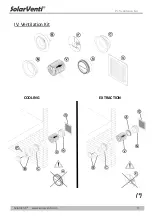
“
COOLING
”
is
used
to
blow
external
non
‐
preheated
air
into
the
building
and
“
EXTRACTION
”
helps
the
airflow
of
the
SV
‐
system.
Summary of Contents for SV14
Page 2: ......
Page 8: ...II Wall Mounting Kit SolarVenti www solarventi com 3 II Wall Mounting Kit ...
Page 10: ...II Wall Mounting Kit SolarVenti www solarventi com 5 2 ...
Page 11: ...II Wall Mounting Kit SolarVenti www solarventi com 6 3 ...
Page 12: ...III Angle Wall Mounting Kit SolarVenti www solarventi com 7 III Angle Wall Mounting Kit ...
Page 13: ...III Angle Wall Mounting Kit SolarVenti www solarventi com 8 ...
Page 14: ...III I Stand Assembly SolarVenti www solarventi com 9 III I Stand Assembly ...
Page 17: ...III I Stand Assembly SolarVenti www solarventi com 12 2 ...
Page 18: ...III I Stand Assembly SolarVenti www solarventi com 13 ...
Page 19: ...III I Stand Assembly SolarVenti www solarventi com 14 3 ...
Page 20: ...IV Ventilation Kit SolarVenti www solarventi com 15 IV Ventilation Kit COOLING EXTRACTION ...
Page 21: ...V Switch SolarVenti www solarventi com 16 V Switch ...
Page 22: ...VI Regulator SolarVenti www solarventi com 17 VI Regulator ...
Page 23: ...Notes SolarVenti www solarventi com 18 Notes ...


