background image

Subject to change | © 2019 SOLARWATT GmbH | AZ-TM-PMS-1339 | Rev 001 | Version: 12/2019

Page 12

5.3.4  Battens for roof tile area

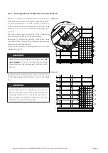
The total spacing between the battens U and O is deter-

mined primarily by the module measurements. There are 

limited change options which are restricted by the roof 
pitch and primarily by the shape and measurements of 

the planned roof tile:


Spacing A is also dependent on the structural height 

of the roof tile above the batten (limit value approx. 
50 mm) and the possibility of grinding higher water 
seams at the top end of the roof tile. 


Possibility of shortening the roof tile (measurement 

K) in the roof tile row above the module field.


Possibility for additional overlap of the top enclosure 

frame by the roof tile (measurement Ü), whereby it 

must be ensured that the inherent load of the roof 

tile must only project over the specified supports in 
the enclosure frame on the roof.


The size of overlap Ü and of shortening K depends on 

the roof tile and the top roof tiling sheet and must be 

determined by a roofer.

If these possibilities are not sufficient, the use of shorter 

or longer roof tiles should be considered, in other words, 

one tile row more or less next to the module field.

Batten spacing LA for the tile area is determined from the 
total spacing between battens U and O which shall also 
then apply to any further tile rows above and below the 

module field.

5.3.5  Optimum number of roof tile rows

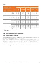
Table  2  on  page  13  includes  for  each  number  of  mod

-

ule  rows  the  respective  optimum  number  of  tile  rows. 

With this number of tile rows there are no dimensional 
overlaps of battens from the module area with battens 

from the tile area. This enables both batten types at the 

left  and  right  edges  of  the  module  field  to  be  pulled 

through to the next counter batten/rafter and fastened 

there. An overlap is only possible with battens for the top 
enclosure frame.

5.3.6  Batten joints between rafters

There may be reasons to select a non-optimal number of 
tile rows so that some battens from the tile area can over-

lap, in full or in part, with battens from the module area. 

In this case the roof statics must be ensured by additional 

vertical and horizontal battens. Chapter 9.2 on page 33 

in the appendix lists a design variant for a transition be-
tween roof batten and aluminum guide rail for a rafter 

spacing of 1.0 m. Transitions between wood battens are 
to be implemented in the same way.

5.3.7  Examples of batten layouts for a roof pitch of 30-65°

Table 2 specifies total spacing D between battens U and 
O as well as batten spacing LA for different roof tile types 
for a structure as in Figure 3 on page 10. Also specified 

are vertical overlap lengths


between the lower dead plate of the SOLARWATT 

roofing frame and roof tiles on batten U


between the roof tiles in the tile area next to the 

module field.

For information on other roof tile types, see Chapter 9.3 
on page 35.

Measurements and spacings for eaves and ridge are not 
included in this, but must be designed separately based 

on the circumstances of the roof.

Summary of Contents for EasyIn 60M Series

Page 1: ...Important Installation and Assembly instructions Read the instructions before starting the installation of the EasyIn modules EasyIn 60M style EN Installation Instructions...

Page 2: ...r roof tile area 12 5 3 5 Optimum number of roof tile rows 12 5 3 6 Batten joints between rafters 12 5 3 7 Examples of batten layouts for a roof pitch of 30 65 12 5 4 Horizontal module field dimension...

Page 3: ...dule connection at the top module field edge 26 6 5 Side module connection 27 6 6 Cable ducting through the roof 28 6 7 Installation of the roof top enclosure frame 29 7 The principle of rear ventilat...

Page 4: ...familiar with installation on the basis of their occupational qualifica tions Modules should be installed and connected only by trained authorized personnel These personnel must be familiarized with...

Page 5: ...perty which could consequently pose a risk to people IMPORTANT Failure to comply with the installation instructions results in the warranty and guarantee becoming null and void and to the exclusion of...

Page 6: ...must absolutely be avoided It is recommended that the SOLARWATT EasyIn modules are stored in a dry and frost free place in their original pack aging until they are installed Please also observe the wa...

Page 7: ...ass II Hail resistance Tested with simulated hailstones 25 mm at 83 km h Fire resistance test DIN ENV 1187 Installation location Upright as roof integration in pitched roofs on buildings up to 18 m hi...

Page 8: ...efore to be laid out and installed on a case by case basis by each install er A few helpful notes will be provided in this regard During the design process of the EasyIn system relevant structural pre...

Page 9: ...ture chosen As specified in the EasyIn planning sheet the minimum spacing between module field and eave must be complied with for the following reasons Increased wind load at the roof edges Construct...

Page 10: ...he eave and ridge and adapt it together with the batten spacing LA to the circumstances of your roof NOTE NOTE NOTE Figure 3 Layout of battens for modules and roofing frame Layout of battens for roof...

Page 11: ...65 B 310 mm for roofing frame 22 29 5 3 3 Battens 1 6 under each module Table 1 Shows another overview of the batten spacings and tolerances for the batten layout underneath the solar module The refe...

Page 12: ...rows Table 2 on page 13 includes for each number of mod ule rows the respective optimum number of tile rows With this number of tile rows there are no dimensional overlaps of battens from the module a...

Page 13: ...132 94 Finkenberger Pfanne 150 0 0 7 296 332 124 88 1 Water seam on the top roof tile end ground down on tiles on batten U 2 Above batten U 5 4 Horizontal module field dimensions 5 4 1 Horizontal mod...

Page 14: ...222 7 237 8 252 9 267 10 282 11 297 12 312 5 4 2 Side batten ends in transition between module and tile field The following figures show the necessary batten projections on the left and right side of...

Page 15: ...Subject to change 2019 SOLARWATT GmbH AZ TM PMS 1339 Rev 001 Version 12 2019 Page 15 Figure 5 Figure 6 Figure 7 Figure 8...

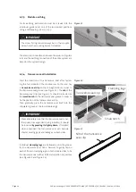
Page 16: ...les or flat headed nails The final fastening is done by applying the counter batten Stricter requirements for fastening counter battens apply in the module field area These are described in Chapter 6...

Page 17: ...head screw 6 x 80 6 2 4 Start of installation with batten U and bat ten 1 First install batten U according to your layout plan As spacing A refers to the top edge of supporting board 98x20 batten 1 i...

Page 18: ...2 7 Laying batten 6 Aluminum guide rail 40x40 on the fastening plate The first aluminum guide rail must be laid with a spacing of 1 642 mm to the top edge of the supporting board 98 x 20 Here it is es...

Page 19: ...il 6 of module row 1 is used as a reference surface Battens 12 13 14 15 and aluminum guide rail 16 are to be arranged in the same way and must be fastened as described in Chapters 6 2 6 to 6 2 7 Compl...

Page 20: ...all any modules in the lowest module row the relevant lower enclosure frame must already be laid there Please always follow the relevant installation instructions for the enclosure frame NOTE NOTE NOT...

Page 21: ...to the batten using two wood screws 6 x 60 with the steepest angle possible between screw and roof batten Screw in the two other mounting brackets in the same way see Figure 19 IMPORTANT Please ensure...

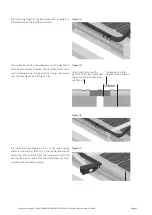
Page 22: ...rse seal groove see Figure 22 The nib of the transverse seal clip see Figure 23 should protrude into the small notch on the transverse seal groove in order to fix the position of the transverse seal c...

Page 23: ...ch supported by using a transverse seal clip see Figure 25 and Figure 26 Figure 24 Figure 25 Small notch to secure the position of the transverse seal clip to the left and right mod ule field side 24m...

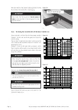
Page 24: ...es both the affixed spacers of module 1 ex pansion gap 2 mm Module 2 is held on the right side by module 1 and is fixed in position with only the 4 mounting brackets on the left side The mounting brac...

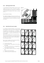
Page 25: ...n a specific instal lation sequence 1 16 which is shown in the figure with an example of a module field with 4 x 4 modules The installation starts in the bottom right corner with Module M1 and progres...

Page 26: ...nection at the top module field edge Shorten all projecting ends of the laid transverse seals on the left and right side of the module field around 3 mm next to the ends of the transverse seal clip Fi...

Page 27: ...oof enclosure frame When using the SOLARWATT roofing frame please consult the installation instructions for the roofing frame Figure 36 NOTE For your own roof enclosure frame you will find design prop...

Page 28: ...re 38 Cable bushing through the inward and outward projecting conduit in the area of the under membrane especially in the case of a converted attic Rainproof and windproof bonding system adhesive tape...

Page 29: ...the air heats up it rises due to its lower density and es capes through the ventilation openings at the roof s ridge or the ventilation tiles to be attached Colder air with higher density is sucked in...

Page 30: ...red parts are in a due and proper condition NOTE If a SOLARWATT EasyIn roofing frame has been purchased also check the delivery of the roofing frame for completeness and correctness of all parts using...

Page 31: ...31 Module connection top long Only for modules in right and left module field corner Module connection top short Aluminum guide rail Fastening plate for aluminum guide rail Wood screw 6 x 60 H Mounti...

Page 32: ...s 40 x 60 mm quality class S10 acc to DIN 4074 Part 1 max wood moisture content at time of installation 20 Supporting board 98 x 20 mm max wood moisture content at time of installation 20 Screws Spax...

Page 33: ...Subject to change 2019 SOLARWATT GmbH AZ TM PMS 1339 Rev 001 Version 12 2019 Page 33 9 Appendix 9 1 Batten layout vertically from bottom to top 9 2 Transition design aluminium guide adjacent batten...

Page 34: ...Subject to change 2019 SOLARWATT GmbH AZ TM PMS 1339 Rev 001 Version 12 2019 Page 34...

Page 35: ...Subject to change 2019 SOLARWATT GmbH AZ TM PMS 1339 Rev 001 Version 12 2019 Page 35 9 3 Total spacing D and LA for different roof tiles...

Page 36: ...2019 SOLARWATT GmbH AZ TM PMS 1339 Rev 001 Version 12 2019 Page 36 9 4 Batten spacings under module field for 1 4 module rows For spacings measured from the top side of supporting board 98 x 20 see Fi...

Page 37: ...own enclosure frames A Cross section metal sheeting in the top frame groove B Module connection top A B 25 Side enclosure frame Top enclosure frame Other measurements are to be specified operationall...

Page 38: ...ule as indicated by SOLARWATT on the respective Solar Module minus a toleran ce range of 5 under Standard Test Conditions irradiance 1 000 W m spectral distribution AM 1 5 temperature 25 2 C hereinaft...

Page 39: ...os records etc must be provi ded at SOLARWATT s request 2 The existence of a Warranty claim event due to the sponta neous breakage of the glass without any external influences or due to a reduced outp...

Page 40: ...happy to help you SOLARWATT GmbH Maria Reiche Str 2a 01109 Dresden Germany Tel 49 351 8895 0 Fax 49 351 8895 100 info solarwatt com Certified acc to ISO 9001 14001 und 50001 BS OHSAS 18001 2007 www so...

Reviews: