Subject to change | © 2019 SOLARWATT GmbH | AZ-TM-PMS-1339 | Rev 001 | Version: 12/2019
Page 28
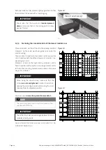
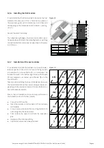
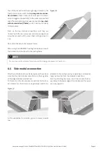
6.6 Cable ducting through the roof
Piping bushings and cable bushings are to be attached
above or to the side of the area covered with the Eas-
yIn modules. A cable bushing between the track supports
is also possible. However only one cable (max. 6 mm²
cross-section) can be bushed and the distance to the oth-
er cables must be at least 10 cm.
In addition, no mounting parts must be located within or
below the area covered with the EasyIn modules, unless
these integrated parts are not located in the water-bear-
ing layer.
For the cable bushing diff erent variants are possible.
Common variants are shown below:
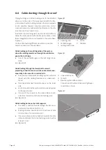
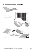
Cable bushing on the roof ridge side of the system
above the sarking membrane through the ventilation
gap on the roof ridge
●
Use of the ventilation gap on the roof ridge is pos-
sible
(see Figure 38)
Cable bushing through the inward and outward
projecting conduit in the area of the under-membrane,
especially in the case of a converted attic
●
Rainproof and windproof bonding (system adhesive
tapes) with the sarking membrane or under-mem-
brane.
●
Pipe penetrates heat insulation layer on the room
side
●
and is air-sealed with a system adhesive tape system
to the vapor barrier.
●
Closure of the conduit on the room-side and roof-
side after completion of the cable bushing work.
(see Figure 39)
Cable bushing between the track supports
●
The cable is bushed inwards through the track sup-
ports which overlap at least 10 cm.
●
Bushing of a max. one cable which must have a cable
cross-section of a maximum 6 mm².
●
If several cables are to be bushed inwards, then the
distance between the cable bushing points must be
at least 10 cm.
(see Figure 40)
Figure 38
A Covering strip
D Cable
B Ventilation gap
E Modules
C Sarking membrane
A
B
C
D
E
Figure 39
A Under-membrane
B Conduit
C Flexible system adhesive tape
Connection of the steam brake/air-tight layer
room side as shown.
A
B
C
Figure 40
10
cm


