DaNGer!
electric shock
The connection of two or more modules in series results in the accumulation of
voltage and imposes danger. Do not insert electrically conductive parts into con-
nectors! Do not attach solar modules and wiring with wet connectors! Make sure
to work with dry tools and under dry working conditions!
Work on live parts
When working on wiring, use and wear protective equipment (insulated tools,
insulated gloves, etc.)!
aTTeNTION
Do not use damaged modules. Do not dismantle modules Do not remove any parts
or nameplates fitted by the manufacturer. Do not apply paint or adhesives to the
module, nor work on it with sharp objects.
WarNING!
arcing
Modules generate direct current (DC) when exposed to light. When breaking a
closed circuit, a dangerous arc may be generated. Do not cut any live wires.
Safe installation
Do not carry out installation work in strong winds. Secure yourself and other per-
sons against falling. Secure work materials against dropping. Ensure a safe working
environment so as to prevent accidents.
fire protection/explosion protection
Modules must not be installed in the vicinity of highly flammable gases, vapors or
dusts (e.g. filling stations, gas tanks, paint spraying equipment). The safety instruc-
tions for other system components must also be followed. Make sure to comply
with local standards, building regulations and accident prevention regulations
during installation. For roof installation, modules must be mounted on a fire-resi-
stant roof covering rated for the application.
Unpacking and intermediate storage
Do not use the junction box as a handle. Do not place modules roughly on hard floor or
on their corners. Do not place modules on top of each other. Do not step or stand on
modules. Do not place any objects on modules. Store modules in a dry place.
Grounding of module and frame
We recommend ensuring the functional grounding of the module metal frame. If an
exterior lightning protection system is already provided, the PV system has to be inte-
grated into the protection concept against direct lightning stroke. Local standards shall
be observed.
1703, may be used for grounding connections in accordance with the instructions provi-
ded with the module. The electrical characteristics are within ±10 percent of the indica-
ted values of ISC, VOC, and Pmax under standard test conditions (irradiance of 100 mW/
cm², AM 1.5 spectrum, and a cell temperature of 25°C (77°F)). Under normal conditions, a
photovoltaic module is likely to experience conditions that produce more current and/
or voltage than reported at standard test conditions. The requirements of the Natio-
nal Electrical Code (NEC) in Article 690-8 shall be followed to address these increased
outputs. To reduce the operating temperature the module has to be mounted on any
surface with a minimum distance of 4 inches (10 cm). In Canada the installation shall
be in accordance with CSA C22.1, Safety Standard for Electrical Installations, Canadian
Electrical Code, Part 1.
Suitable ambient conditions
Artificially concentrated sunlight shall not be directed on the module or panel. The
module must neither be immersed in water nor be exposed to continuous wetting (e.g.
by fountains). Exposure to salt or sulfur (sulfur sources, volcanoes) implies a risk of cor-
rosion. The module must not be used for maritime (e.g. boats) or automotive (vehicles)
purposes. The module must not be exposed to extraordinary chemical loads (e.g. emis-
sions from manufacturing plants). If the modules are installed on stables, a distance of
3.28 ft (1 m) to ventilation openings shall be ensured; apart from this, the modules shall
not be used as a direct roof panel on stables.
appropriate installation situation
Make sure that the module meets the technical requirements of the overall system.
Other system components should not exert any adverse mechanical or electrical influ-
ences on the module. Modules may bend under high loads. For this reason, sharp-edged
fixing elements or other sharp objects (e.g. cable ties on mounting sections must not
be mounted near the module back side. For modules connected in series, only modules
of the same amperage rating may be used together. For modules connected in paral-
lel, modules with the same voltage ranges must be used together. The modules must
not be operated at a higher voltage than the permissible system voltage. The inside
opening of the frame corner element is intended for water drainage and must not be
blocked. For system documentation, please note the serial numbers.
Optimum installation
In order to avoid performance losses, all modules connected in series should be
arranged with the same orientation and tilt angle. The modules should be installed in
an all-season shadow-free area. Even partial shadowing results in yield losses and is to
be avoided. Ventilation of the module back side will prevent heat build-up adversely
affecting performance.
Mounting
The modules must be securely fixed at a minimum of 4 locations on the substruc-
ture. Fixing is only allowed in designated areas. In regards to “Top-Down” mounting
methods, the maximum clamping pressure is 50 N/mm² (72.5 psi). Do not drill any holes
into the module. Use corrosion-proof fixing material.
electrical connection
The modules are provided with factory-assembled cables and connectors . Do not open
the junction box in any case. Connectors may only be connected under dry conditions.
Make sure to avoid gaps in a plugged connection. Only singlecore solar cables with an
adequate cross-section (2.5 mm² or 14 AWG minimum) and appropriate connectors
may be used for connecting the modules. Cables should be attached to the installation
system by means of UV-resistant cable ties. Exposed cables should be protected against
sunlight and damage by suitable precautions (e.g. conduits) In order to limit voltages
released by indirect lightning shock, the area of all conductor loops must be reduced
to a minimum. Check that wiring is correct (polarity!) prior to starting the generator.
Cleaning
In general, the modules do not need any cleaning if the tilt angle is sufficient
(> 15°; self-cleaning by rain). In case of heavy soiling, we recommend cleaning the modu-
les with plenty of water (ap water or deionized water) without any cleaning agents.
If necessary, a soft cleaning device (sponge.g. soft brush with split bristles) maybe be
used. In case of soiling by dust or sand the modules can be cleaned with a soft brush
without using water. Never scrape or rub off dirt; this may result in micro-scratches.
Maintenance
We recommend regular inspections of the system to ensure that:
1. All fixtures are securely tightened and corrosion-free;
2. Wiring is securely connected, properly arranged and free of corrosion;
3. Cables are free of damage;
Please also observe applicable standards.
Disclaimer of liability
SolarWorld AG does not guarantee the operational capability and functionality of
modules if the instructions contained in the present user information are not complied
with. Since compliance with these instructions and the conditions and methods of
installation, operation, use and maintenance of the modules are not checked or moni-
tored by SolarWorld AG, SolarWorld AG accepts no liability for damage arising through
improper use or incorrect installation, operation, use or maintenance. Furthermore, lia-
bility for infringements of patent law or of other third party rights arising from the use
of the modules is excluded unless we are automatically liable by law.
EN
General Information
This module is rated for use in application class A according to IEC 61730. For the elec-
trical ratings please refer to the datasheet. Under normal conditions, a photovoltaic
module is likely to experience conditions that produce more current and/or voltage
than reported at standard test conditions. Accordingly, the values of ISC and VOC mar-
ked on this module should be multiplied by a factor of 1,25 when determining compo-
nent voltage ratings, conuctor current ratings, fuse sizes, and size of controls connected
to the PV output.“
Underwriters Laboratories Information (U.S. and Canada)
The fire rating of this module is valid only when mounted in the manner specified in
the mechanical mounting instructions. The module is considered to be in compliance
with UL 1703 only when the module is mounted in the manner specified by the moun-
ting instructions below. A module with exposed conductive parts is considered to be
in compliance with UL 1703 only when it is electrically grounded in accordance with
the instructions presented below and the requirements of the National Electrical Code.
Where common grounding hardware (nuts, bolts, star washers, spilt-ring lock was-
hers, flat washers and the like) is used to attach a listed grounding/bonding device, the
attachment must be made in conformance with the grounding device manufacturer’s
instructions. Common hardware items such as nuts, bolts, star washers, lock washers
and the like have not been evaluated for electrical conductivity or for use as grounding
devices and should be used only for maintaining mechanical connections and holding
electrical grounding devices in the proper position for electrical conductivity. Such devi-
ces, where supplied with the module and evaluated through the requirements in UL
B)
a)
1
2
1
3
4
5
6
Grounding in the US and Canada
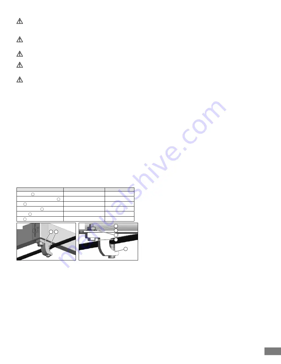
The modules can be connected at the module corner (A). For frames with flange the
modules can be connected at the holes provided in the flange (B). The lug must be a
tin-coated copper lug, silver in color. Do NOT use a bare copper lug, which is brown.
Any grounding method and components listed according to NEC requirements are also
acceptable in the US and Canada.
Table: recommended components for grounding in the US and Canada
Item
Manufacturer/Description
Tightening torque
Lay-In lug 1
Ilsco GBL-4DBT (E34440)
Type F Thread Cutting Screw 2 SS #10-32
32 Ibf-in (3.6 Nm)
Bolt 3
#10-32, SS
25 Ibf-in (2.9 Nm)
Serrated washer 4
M5, SS
Washer 5
ID 9/64’’, OD 3/8’’, SS
Nut 6
#10-32, SS


