15 |
P a g e
Connection: Controller to Storage Water Vessel
1.
Remove lower DC element cover (figure2).
2.
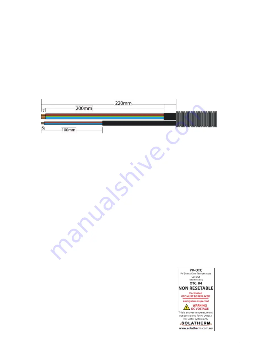
Route the 2.5m long flexible element output cable to the bottom element
inlet conduit elbow and thread both cables though up into element
cavity. It may be necessary to use a wire hook to help thread/ pass the 2 x
cables through the elbow. (It is important to have the first outer
insulation cover removed 200mm back exposing the 3 x insulated wires,
as passing the complete cable through the elbow is very tight). (Figure 6)
3.
Terminate the element positive, negative & earth as per the instruction
label that is affixed to the inside of the element enclosure cover and per
the labelled colour coded connection points within.
4.
Connect the 2 x colour coded NTC sensor wires into colour coded
mounting block.
See Figure 7: Wiring Diagram - PV OTC - Element
5.
Ensure PVOTC which is spring located onto vessel surface has not been
disturbed during installation and is sitting in place and secure. Re-install
DC element cover (Figure 2).
6.
Using the supplied cable saddles and removing and replacing base lid
screws to fit saddles, secure supply cable securely to the base of the hot
water tank.
7.
Connect NTC connector to controller base.
PVOTC is only activated by overheating of the storage
vessel which indicates a potential system fault. The PVOTC
is a onetime operation and is NON RESETABLE. If activated
the PVOTC must be replaced.
Figure 6


