21 |
P a g e
Commissioning Start Up
1.
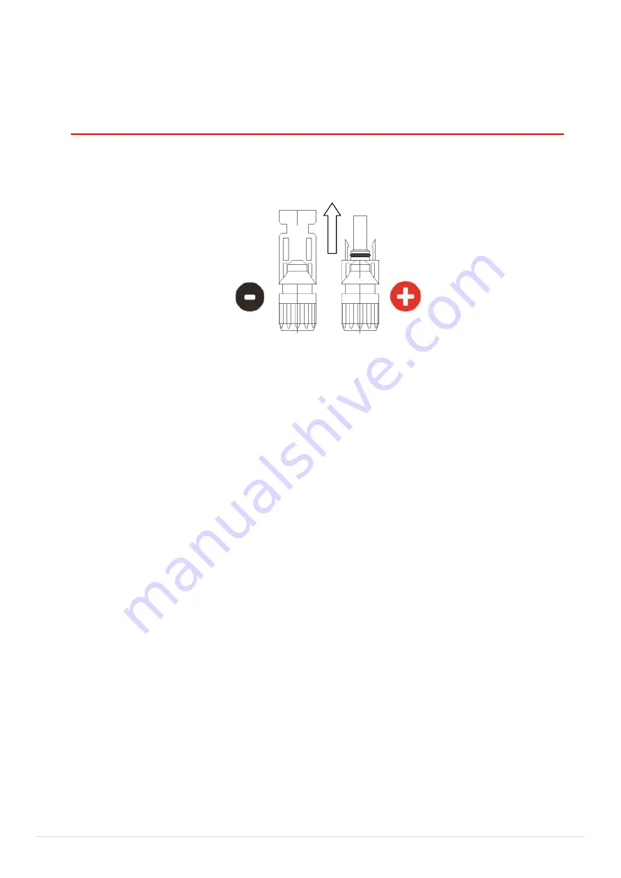
Ensure polarity at the MC4 connectors is correct before proceeding
further.
TEST CONNECTORS BEFORE CONNECTION INTO THE CONTROLLER (PCE)
2.
TURN ISOLATOR ON AND TEST CORRECT POLARITY TO CONFIRM BEFORE
PROCEEDING. Figure 11.
3.
Test voltage from array. Confirm correct for controller model.
4.
Connect MC4 connectors to control unit.
5.
Turn on isolator.
6.
RED LED POWER LIGHT SHOULD BE ON. The controller should show start up
information as it runs though a power up test sequence. When test is
complete LCD will display system voltage etc. (providing array voltage is
over 40 Volts)
7.
After the start up sequence is complete the green heating LED will light up if
sufficient power is available to commence heating. Note: The controller has
several built in time delays of up to 1.5 minutes, to allow for power
stabilisation. Some models will start on divert for 30min prior to heating.
See supplement.
8.
Turn on 240V AC booster isolator and breaker switch in household fuse box.
9.
Test and record data on the Commissioning sheet in this booklet and make
a copy for submission to Solatherm. Form A
Shut down Procedure
1.
Turn off main array Isolator (lock switch if required)
2.
Controller should now have no information displayed and is OFF.
3.
Turn off 240V AC Booster Isolator and breaker switch in household fuse
box.
Positive on loom
from the Isolator
Negative on the loom from
the isolator
To Controller
From Array
Figure 11


