3
ALLINONE
PHOTOVOLTAIC MODULES
ENG
ITA
RISKS FROM MECHANICAL DAMAGE
The photovoltaic cells contained in SolbianFlex modules are fragile. The manufacturing technology of the modules provides
protection for the cells, provided that certain precautions are taken.
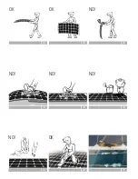
SolbianFlex modules are flexible, but they cannot be rolled-up or
folded. The minimum allowed curvature radius is 1 m. For a 1 m
long module, the maximum arc (F) is 122 mm.
Excessive bending must be avoided when handling the modules.
See Fig. 1 for correct handling. The module may be handled by
the edge (Fig. 2), but only if it is held vertically and without exerting excessive pressure to the edges of the cells. The modules
should not be held by the short ends or corners as this may cause excessive bending under their own weight (Fig. 3).
SolbianFlex modules may be walked on, but only when they are firmly mounted on a flat, smooth, rigid surface, with no bumps,
hollows or irregularities (Fig. 4), taking care, barefoot or with soft-soled shoes, avoiding heels and shoes with a rigid sole (Fig. 5).
Uninstalled modules or modules in removable installations (using eyelets, snap fastners etc.) must not be walked on.
If sharp or heavy objects are allowed to fall onto the modules, they can cause fractures in the cells (Fig. 7).
If, during installation or maintenance, it is necessary to kneel on the module, it is advised to use adequate protection, to avoid
damaging the cells (Fig. 8).
HOT-SPOT
A module containing damaged cells, or even a module in good condition in which one or a small number of cells are completely
shaded (Fig. 6), can suffer from a HOT-SPOT, i.e. local overheating, even up to the point of causing the protective material to
smoke and reach temperatures over 200°C (392 °F) on small areas.
In principle, this phenomenon could cause a fire, a danger which is always present where electrical apparatus is used. However,
normally the damage is limited to small local burning as in the examples shown in Fig. 9.
In the event of HOT-SPOTS forming, the module must be disconnected immediately.
In this way, the flow of current is
stopped and further temperature rises are avoided. As an alternative, it is possible to cover the module, to avoid exposure to light.
In the case of several modules connected in series, the only solution is to disconnect the module.
MECHANICAL INSTALLATION
P
Do not bend the modules with a radius of bending less than 1m, otherwise the photovoltaic cells could be permanently
damaged.
P
SolbianFlex modules alone cannot withstand the loads caused by high winds or snow. The installation must bear in mind
the structural resistance of the modules’ support. The structure must not be continually subjected to stress. Improper use
of SolbianFlex modules can cause irreversible damage to the system, thereby compromising the efficiency and usage of the
system.
P
The position of the installation should take advantage of the maximum exposition to the sunlight and the minimum shading.
Remember that even partial shading of the module can cause a substantial reduction in the amount of energy produced. Do
not place objects on the modules exposed to the light (Fig. 6).
P
The position of SolbianFlex modules must allow adequate circulation of air on the surfaces exposed to sunlight. This is
sufficient to lower the temperature and ensure high efficiency
INSTALLATION WITH EYELETS/SCREWS
SolbianFlex modules may be supplied with metal eyelets for installation. In this case, the modules are fixed using ropes, straps
or other similar devices, to rigid surfaces which support the modules and resist atmospheric agents. Holes may be used to screw
the modules to a rigid surface, in the same position as the eyelet holes. In both cases,
the modules cannot be walked on
.
INSTALLATION USING LOXX FASTENERS
LOXX fasteners are special steel clips which allow easy fixing and removal of the modules. They can be used for mounting onto
rigid surfaces or onto textiles, such as the Bimini on a boat or tents etc. Different LOXX fasteners are suitable for the two types
of installation.
Summary of Contents for ALLINONE
Page 2: ...3 OK OK NO 1 2 3 NO NO NO 4 5 6 NO OK 8 9 7...
Page 3: ...7 Installation manual Manuale di installazione...
Page 15: ......


