15
Recommended Wiring Scheme
________________________________________________________________________________________
x
The sinusoidal shape of the current is imperfect (since each phase is separately fired
and not influenced by other phase firing).
As a result, higher harmonic content is incurred (THD), which can be as high as twice
WKH7+'YDOXHDVLQWKHVWDQGDUG³,Q
-
/LQH´
x
Higher
motor
heating
is
expected for the same motor size (due to the higher THD).
x
3KDVHVHTXHQFHPXVWEHFRUUHFWRWKHUZLVH³3KDVH6HTXHQFHIDXOW´ZLOOWULSWKH
starter immediately (without any damage).
x
Higher torques can not be obtained
x
Factory
preset
-
feat
XUHVDQGIXQFWLRQVZKHQ³,QVLGH'HOWD´PRGHLVFRQILJXUHG
o
No Pulse Start.
o
No curve selection (Curve 0 !! only).
o
No Slow Speed
o
1R3KDVHVHTXHQFH³2II´PRGH
Note :
)RUDKLJKVWDUWLQJWRUTXHSURFHVVLWLVUHFRPPHQGHGWRXVHWKHVWDUWHULQWKH³,Q/LQH´FR
nnection.
WARNINGS!
Beware!
Wrong connection of the starter or the Motor, will seriously damage the motor.
:KHQXVLQJ³,QVLGHGHOWD´FRQQHFWLRQ
1. It is highly recommended to use a contactor in series to the RVS-DXM
or upstream (after motor protection) in order to avoid a destruction of the
motor in case of a shorted SCR in the RVS-DXM.
,I&RQWDFWRULVFRQQHFWHG,QVLGHWKH'HOWDPRWRUWHUPLQDOVDUH³OLYH´IXOO
voltage) even when contactor is open.
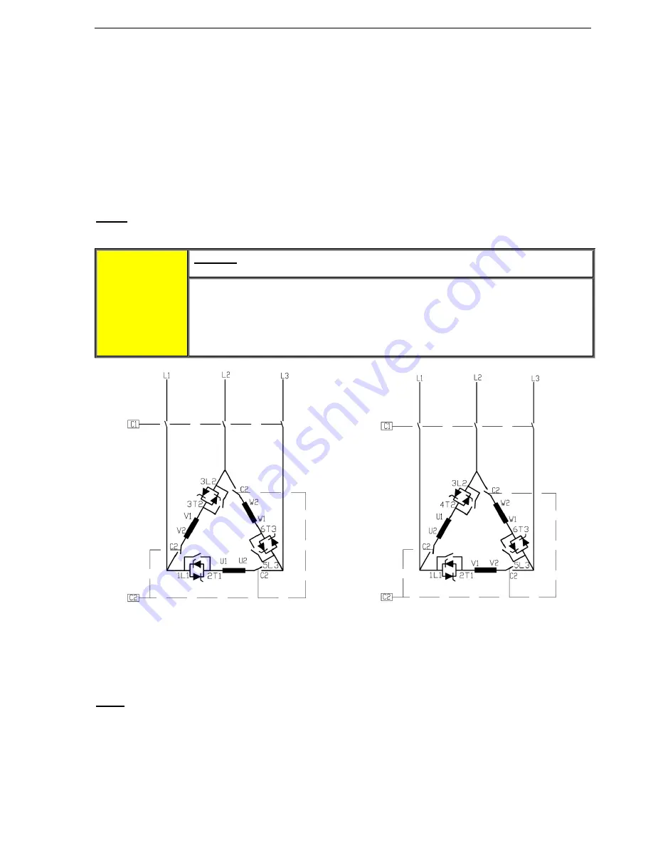
RVS-DXM connected INSIDE DELTA
Speed reverse with RVS-DXM connected
INSIDE DELTA
(1) C1 is a line contactor.
(2)
&LVDQ³,QVLGH'HOWD´FRQWDFWRU
(3) U1-U2, V1-V2, W1-W2
DUHPRWRU¶VZLQGLQJV
(4) L1-U, L2-V, L3-W are RVS-DXM controlled phases.
Refer also to section
4.4 page 13.
Note:
Motor terminals are marked as follows:
ASA (USA)
BS
VDE
IEC
T1 - T4
A1-A2
U - X
U1 - U2
T2 - T5
B1-B2
V - Y
V1 - V2
T3 - T6
C1-C2
W - Z
W1 - W2


