ns. rif:
SI003-033
GB
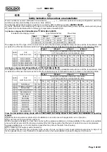
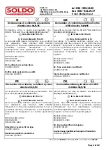
Safety instruction to hazardous area installation
Model numbers covered: limit switch box series SI_ _ _ _ _ _-_ ( _ indicates options in housing configuration, switches,
switches quantity, terminal strip, box colour, cable entries).
The following instructions apply to equipment covered by ATEX certificate number
03ATEX 135107X
1)
The SI limit switch box series may be used in an hazardous area with flammable gases, vapours, dust and mist, group
IIC, protection mode EEx ia with the following temperature classes T4,T5,T6.
1a) Device category 2G, EX identification
II 2 G EEx ia IIC T6
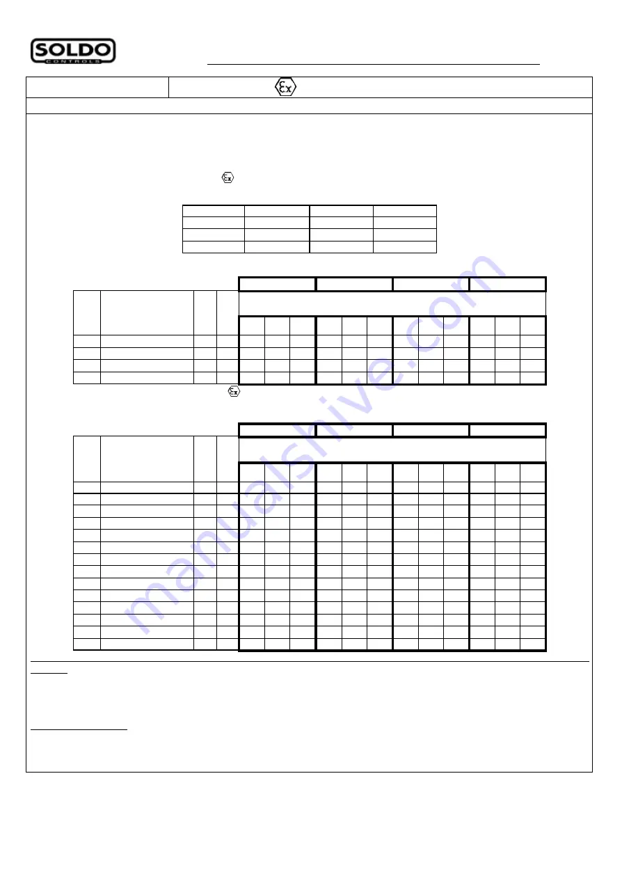
Evaluation and supply circuit Type Intrinsic Safety Max value
Type 1
Type 2
Type 3
Type 4
U
i
i
i
=
=
=
16 V
U
i
i
i
=
=
=
16 V
U
i
i
i
=
=
=
16 V
U
i
i
i
=
=
=
16 V
I
i
= 25 mA
I
i
= 25 mA
I
i
= 52 mA
I
i
= 76 mA
P
i
= 34 mW P
i
= 64 mW P
i
= 169 mW P
i
= 242 mW
The assignment of the type of the connected circuit to the maximum permissible temperature and the temperature class
as well as the effective internal reactances for the individual types of limit switch boxes are shown in the following table:
Type 1
Type 2
Type 3
Type 4
Maximum permissibile ambient temperature
in C° for application in temperature class
Soldo
Code
P +F
switches code
C
i
i
i
(nF)
L
i
i
i
(?H)
T6
T5
T4
T6
T5
T4
T6
T5
T4
T6
T5
T4
SI_20
NJ4-12GK-N
45 50
73
88 100 69
84 100 51
66 80
39
54 61
SI_24
NJ2-12GK-N
45 50
73
88 100 69
84 100 51
66 80
39
54 61
SI_59 NCB2-12GK35-N0 90 100 76
91 100 73
88 100 62
77 81
54
63 63
SI_61 NCN4-12GK35-N0 95 100 73
88 100 69
84 100 51
66 80
39
54 61
1b) Device category 2GD, EX identification
II 2 G/D EEx ia IIC T6
The assignment of the type of the connected circuit to the maximum permissible temperature and the temperature class
as well as the effective internal reactances for the individual types of limit switch boxes are shown in the following table:
Type 1
Type 2
Type 3
Type 4
Maximum permissibile ambient temperature
in C° for application in temperature class
Soldo
Code
P +F
switches code
C
i
i
i
(nF)
L
i
i
i
(?H)
T6
T5
T4
T6
T5
T4
T6
T5
T4
T6
T5
T4
SI_28
NJ2-11N-G
30 50
76
91 100 73
88 100 62
77 81
54
63 63
SI_30 NCB2-12GM35-N0 90 100 76
91 100 73
88 100 62
77 81
54
63 63
SI_36
NJ5-11-N-G
45 50
72
87 100 65
80 100 42
57 82
26
41 63
SI_37 NCN4-12GM35-N0 95 100 76
91 100 73
88 100 62
77 81
54
63 63
SI_39
NJ2-12GK-SN
50 150 73
88 100 69
84 100 51
66 80
39
54 61
SI_50
NJ2-11SN-G
50 150 76
91 100 73
88 100 62
77 81
54
63 63
SI_60
SJ-3.5-N
50 250 73
88 100 66
81 100 45
60 89
30
45 74
SI_62
SJ-3.5-SN
30 100 73
88 100 66
81 100 45
60 89
30
45 74
SI_63
SJ-3.5-S1N
30 100 73
88 100 66
81 100 45
60 89
30
45 74
SI_68
NJ5-11-N
45 50
72
87 100 65
80 100 42
57 82
26
41 63
SI_69
NJ2-11-N
45 50
73
88 100 66
81 100 45
60 89
30
45 74
SI_70
NJ2-V3-N
40 50
73
88 100 66
81 100 45
60 89
30
45 74
SI_84
NJ2-11-SN
50 150 73
88 100 66
81 100 45
60 89
30
45 74
SI_86
NJ4-12GK-SN
70 150 73
88 100 69
84 100 51
66 80
39
54 61
Cross the temperature rating shown with the limit switch box rating shown in limit switch box installation & operating
manual.
2)
Suitably trained personnel shall carry out installation in accordance with applicable code of practice
3)
The user should not repair this equipment.
4)
If the equipment is likely to come into contact with aggressive substances, it is responsibility of the user to take suitable
precautions that prevent it from being adversely affected, thus ensuring that the type of protection is not compromised.
Agressive substances – es. Acidic liquids or gases that may attack the switch box housing.
5)
The following precaution must be observed:
The metallic alloy used for the enclosure, in the event of a rare accident, could cause ignition sources due to impact or
friction (sparks may occur). This shall be considered when the box is installed in group II category 2 G/D areas.
Pag. 3 of 22
Summary of Contents for SIF Series
Page 14: ...Pag 14 of 22...
Page 15: ...Pag 15 of 22...
Page 16: ...Pag 16 of 22...
Page 17: ...Pag 17 of 22...
Page 18: ...Pag 18 of 22...
Page 19: ...Pag 19 of 22...
Page 20: ...Pag 20 of 22...
Page 21: ...Pag 21 of 22...
Page 22: ...Pag 22 of 22...

