Soldo S.r.l.
Via Monte Baldo, 60
25015 Desenzano d/G (Brescia) Italy
Tel +39 030 999.13.09 - Fax +39 030 914.19.77
http: //www.soldo.net
e-mail: sales@soldo.net
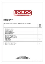
Installation & Operating Manual
Manuale d’installazione
Installations und Betriebsanleitung
Manuel d’installation et d’utilisation
IOM-SIF.SIS00-02
SIF
SIS
IOM-SIF.SIS00-02
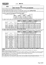
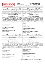
GB
READ THIS INSTRUCTION FIRST
To avoid serious or fatal personal injury or major property
damage, read and follow all safety instruction in this manual.
If you require additional assistance, please contact the
manufacturer.
SAVE THIS INSTRUCTION
SAFETY ALERT SYMBOLS
DANGER
Warns of hazard that WILL cause serious personal
injury, death or major property damage.
WARNING
Warns of hazard that MAY cause serious personal
injury, death or major property damage.
CAUTION
Warns of hazard that MAY cause personal injury or
property damage.
WARNING !
HAZARDOUS VOLTAGE. Disconnect all power before servicing
equipment. DO NOT REMOVE COVER WHEN ENERGISED.
CAUTION !
Do not exceed the limit switch performance limitation. Exceeding
the limitation may cause damage to the limit switch, actuator and
valve
.
The conduit plug supplied with the switch boxes are for transit
purposes only. IP67 protection depends on cable gland and cabling
methods used.
Limit switchbox for quarter-turn valve device (90° rotation).
Maximum shaft angular velocity 250 rpm.
Follow switch adjustment & indicator setting before servicing the
limit switch box.
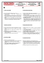
1e INSTALLATION
1.1 Attach proper mounting bracket (1) to the box (4) housing
using four M 6X8 bolts (2).
1.2 Align shaft (5) to actuator shaft and engage it.
1.3 Attach bracket (1) to actuator using hardware provided (3).
IT
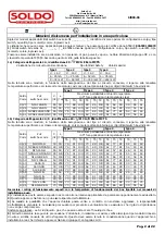
PRIMA DI INSTALLARE IL BOX LEGGERE QUESTE ISTRUZIONI
Per evitare il ferimento, la morte o danni importanti a oggetti
leggere e seguire tutte le istruzioni di sicurezza presenti in
questo manuale. Se vi servono informazioni aggiuntive non
esitate a contattate il produttore.
CONSERVATE QUESTE ISTRUZIONI
SIMBOLI DI SEGNALAZIONE PERICOLO
DANGER
Segnalazione di pericolo che causerà serie ferite, morte
o danni importanti a oggetti.
WARNING
Segnalazione di pericolo che potrà causare serie ferite,
morte o danni importanti a oggetti.
CAUTION
Segnalazione di pericolo che potrà causare ferite o
danni a oggetti.
WARNING !
PERICOLO SCOSSE ELETTRICHE. Togliere l’alimentazione elettrica
prima di collegare o manutenere l’apparecchio. NON TOGLIERE IL
COPERCHIO CON L’APPARECCHIO IN TENSIONE
CAUTION !
Non superare le limitazioni di utilizzo degli switch. Il superamento
delle limitazioni può causare il danneggiamento degli switch, dell’
attuatore o della valvola.
I tappi di protezione dell’ingresso cavi forniti a corredo di ogni switch
box servono solo come protezione durante il trasporto e non
garantiscono il grado di protezione IP 67. Vanno pertanto sostituito, in
fase di installazione, con pressa cavo che garantiscano il grado di
protezione richiesto.
Limit switch box per uso su valvole a quarto di giro (90° di rotazione).
Massima velocità di rotazione dello stelo 250 rpm. Non rispettando
questa indicazione si producono danni.
Seguire la procedura di taratura camme e regolazione indicatore
prima di mettere in servizio il limit switch box.
1i INSTALLAZIONE SULL’ATTUATORE
1.1 Fissare la staffa (1) al corpo del box (4) utilizzando le 4 viti a
cava esagonale M 6x8 (2).
1.2 Ruotare manualmente lo stelo (5) in modo che il lembo fresato
sia parallelo alla cava situata sul pignone dell’attuatore, quindi
innestarlo alla stessa.
1.3 Fissare la staffa (1) all’attuatore con le viti fornite a corredo (3).
Pag. 7 of 22
Summary of Contents for SIF Series
Page 14: ...Pag 14 of 22...
Page 15: ...Pag 15 of 22...
Page 16: ...Pag 16 of 22...
Page 17: ...Pag 17 of 22...
Page 18: ...Pag 18 of 22...
Page 19: ...Pag 19 of 22...
Page 20: ...Pag 20 of 22...
Page 21: ...Pag 21 of 22...
Page 22: ...Pag 22 of 22...

