Soldo S.r.l.
Via Monte Baldo, 60
25015 Desenzano d/G (Brescia) Italy
Tel +39 030 999.13.09 - Fax +39 030 914.19.77
http: //www.soldo.net
e-mail: sales@soldo.net
Installation & Operating Manual
Manuale d’installazione
Installations und Betriebsanleitung
Manuel d’installation et d’utilisation
IOM-SIF.SIS00-02
SIF
SIS
IOM-SIF.SIS00-02
GB
2e SWITCH ADJUSTMENT
2.1 Loose the screws (8) and remove box cover (7).
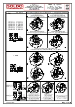
2.2 Follows indication in “Cams setting – Regolazione delle
Camme” Page 11.
2.3 Box with 3-4 switches, set the actuator in the extra position you
have to signal. Act according to indications in “Cams setting –
Regolazione delle Camme” to set cams of the switch number 3
and 4.
2.4 Replace box cover (7). WARNINGS: check seal (6) is properly
fitted in slot. Turn manually cover’s shaft (15) cheeking to align
it to switch box shaft and engage it. Tightening screws (8).
3i 3D INDICATOR SETTING
3.1 Remove four screws (13) and remove 3D indicator’s cover (12).
3.2 Remove screw (10) and lift up 3D indicator from its splined
retainer.
3.3 Set 3D indicator (9) on splined retainer according to valve
position.
3.4 Fix 3D indicator (9) screwing the (10) screw.
3.5 Replace 3D Indicator cover (12). WARNINGS: check seal (11)
is properly fitted in slot.
3.6 Reassemble 3D-indicator cover by the screws (13).
4e
ELECTRICAL WIRING
4.1 Remove cover (7) according point 2.1.
4.2 Remove protection plugs from cable entries and substitute them
with cable glands or plugs suitable for type of protection
required.
4.3 Connect terminal strip (14) according to the wiring diagram in
“Cams setting – Regolazione delle Camme” Page 11.
4.4 Reassemble cover (7) according to point 2.4.
IT
2i REGOLAZIONE DEI FINECORSA
1.1 Svitare le quattro viti (8) e rimuovere il coperchio (7).
1.2 Seguire le indicazioni della tabella “Cams setting – Regolazione
delle Camme” page 11.
1.3 Se box con 3-4 micro, portare l’attuatore nelle altre posizioni in
cui si desiderano le segnalazioni. Regolare le camme per i micro
3 e 4 agendo come da indicazioni della tabella “Cams setting –
Regolazione delle Camme”.
1.4 Riposizionare il coperchio (7) sul box (4). ATTENZIONE verificare
che la guarnizione (6) si alloggiata nella apposita cava. Per
effettuare questa operazione ruotare manualmente lo stelo (15)
del coperchio in modo che il lembo fresato sia parallelo alla cava
situata sul stelo del box, quindi innestarlo allo stesso. Serrare le
viti (8).
3i REGOLAZIONE INDICATORE 3D
3.1 Svitare le quattro viti (13) e sollevare il coperchio dell’indicatore
3D (12).
3.2 Svitare la vite (10) e tirando verso l’alto sfilare l’indicatore 3D (9)
dal suo supporto millerighe.
3.3 Innestare l’indicatore 3D (9) sul millerighe curando che la sua
posizione rispecchi la posizione della valvola.
3.4 Fissare l’indicatore av vitando la vite (10).
3.5 Rimontare il coperchio dell’indicatore 3D (12) curando che la
guarnizione (11) sia correttamente alloggiata nella sua cava.
3.6 Avvitare le viti di fissaggio (13) del coperchio dell’ indicatore 3D.
4i CABLAGGIO ELETTRICO
4.1 Rimuovere il coperchio (7) come indicato nel punto 2.1.
4.2
Rimuovere i tappi di protezione e sostituirli con pressacavo/i ed/o
tappo/i filettati, che garantiscano il livello di protezione richiesto.
4.3 Collegare i morsetti (14) utilizzando un cacciavite con testa a
taglio max. 3,5 mm e seguendo lo schema corrispondente (pag.
11).
4.4 Rimontare il coperchio (7) come indicato nel punto 2.4.
Pag. 9 of 22
Summary of Contents for SIF Series
Page 14: ...Pag 14 of 22...
Page 15: ...Pag 15 of 22...
Page 16: ...Pag 16 of 22...
Page 17: ...Pag 17 of 22...
Page 18: ...Pag 18 of 22...
Page 19: ...Pag 19 of 22...
Page 20: ...Pag 20 of 22...
Page 21: ...Pag 21 of 22...
Page 22: ...Pag 22 of 22...

