background image

Dyaco Canada Inc. 2013


28 

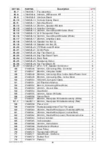
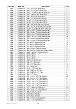
KEY NO.


PART NO. 

Description 

Q

’TY


45~7 

17303545-7


Fan Assembly 

45~8 

17303545-8


300m/m_W/Receiver, HR 

45~9 

17303545-9


Interface Board 

45~10 

17303545-10


Console Display Board 

45~11 

17303545-11


Main Key Board 

45~12 

17303545-12


250m/m_Speaker W/Cable 

45~13 

17303545-13


Amplifier Controller 

45~14 

17303545-14


300m/m_Sound Board W/Cable (Red) 

45~15 

17303545-15


LCD Transparent Piece 

45~16 

17303545-16


300m/m_Sound Board W/Cable (White) 

45~17 

17303545-17


250m/m_Amplifier Cable 

45~18 

17303545-18


Speaker Iron Net (L) 

45~19 

17303545-19


Speaker Iron Net (R) 

45~20 

17303545-20


7.5"Water-resist Rubber 

45~21 

17303545-21


LOGO Plate 

45~22 

17303545-22


Key Fast Board (L) 

45~23 

17303545-23


Key Fast Board Foam 

45~24 

17303545-24


Book Rack 

45~25 

17303545-25


Resistance Button 

45~26 

17303545-26


Key Fast Board (R) 

45~27 

17303545-27


Ø12 × 5.5T_Speaker Grill Anchor 

46 

17303546


300m/m_Connecting Wire, Controller 

47 

17303547


850m/m_Computer Cable 

48 

17303548


900m/m_Connecing Wire, Incline Motor Power Cord 

49 

17303549


850m/m_Connecting Wire, Incline Motor 

50 

17303550


1550m/m_Computer Cable 

51 

17303551


AC Electronic Module 

52 

17303552


80m/m_Connecting Wire (White) 

53 

17303553


200m/m_Ground Wire 

54 

17303554


Gear Motor 

55 

17303555


400m/m_Sensor W/Cable 

56 

17303556


Sensor Rack 

57 

17303557


850m/m_Handpulse W/Cable Assembly (White) 

57~1 

17303557-1


850m/m_Handpulse W/Cable Assembly (Red) 

58 

17303558


Power Cord 

59 

17303559


Handpulse Adjustment Thin Film Label 

60 

17303560


450m/m_Handle Wire (Upper), Resistance(White) 

61 

17303561


450m/m_Handle Wire (Upper), Incline(Red) 

62 

17303562


900m/m_Handle Wire (Lower), Resistance/Incline 

64 

17303564


Incline Controller 

65 

17303565


Incline Adaptor 

66 

17303566


400m/m_Audio Cable 

68 

17303568


Handle Switch Bracket 

69 

17303569


Drive Pulley 

70 

17303570


Transportation Wheel 

71 

17303571


Slide Wheel , Urethane 

72 

17303572


Rubber Foot 

73 

17303573


Pedal (L) 

Summary of Contents for 168173035

Page 1: ...Model 168173035 OWNER S MANUAL PLEASE CAREFULLY READ THIS ENTIRE MANUAL BEFORE OPERATING YOUR NEW ELLIPTICAL...

Page 2: ...yInstructions 10 Elliptical Features 14 Operation ofYour New Elliptical 15 Programmable Features 17 Using Heart Rate Monitor 23 General Maintenance 25 Exploded View Diagram 26 Parts List 27 Manufactur...

Page 3: ...1 888 707 1880 If you purchased this fitness product from Sears they will be your contact for all service needs To contact Sears for any service issues call 1 800 4 MY HOME 1 800 469 4663 Please take...

Page 4: ...are obvious pinch points and other caution areas that can cause harm Keep hands away from all moving parts Never operate the elliptical if it has a damaged cord or plug If the elliptical is not workin...

Page 5: ...on surfaces GROUNDINGINSTRUCTIONS This product must be grounded If the elliptical should malfunction or breakdown ground ing provides a path of least resistance for electric current reducing the risk...

Page 6: ...ts Unplug the elliptical during an electrical storm as a precaution Use caution while participating in other activities while using your elliptical such as watching television reading etc These distra...

Page 7: ...81 3 8 x 23 x 2T Curved Washer 2 pcs 180 3 8 x 2T Split Washer 1 pc 141 M5 x 10mm Phillips Head Screw 4 pcs 157 3 8 x 7T Nylon Nut 2 pcs 182 5 16 x 1 5T Split Washer 4 pcs 183 5 16 Star Washer 4 pcs 1...

Page 8: ...Sheet Metal Screw 18 pcs 145 M6 x 10mm Phillips Head Screw 4 pcs 2HARDWARESTEP2 3HARDWARESTEP3 4HARDWARESTEP4 132 3 8 x 3 4 Hex Head Bolt 2 pcs 134 5 16 x 1 1 4 Hex Head Bolt 2 pcs 165 3 8 x 30 x 2T...

Page 9: ...x along the dotted Line Lift Box over the unit and unpack 2 Carefully remove all parts from carton and inspect for any damage or missing parts If damaged parts are found or parts are missing contact y...

Page 10: ...nto the receiving bracket on the top of the Main Frame 1 Pull slightly on the Computer Cable at the top of the mast while installing This will ensure the cable does not get pinched and shorted during...

Page 11: ...Dyaco Canada Inc 2013 11 1ASSEMBLYSTEP 1 2ASSEMBLYSTEP 2...

Page 12: ...o each joint 3 Match up the outer Connecting Arm Covers 109 110 and install onto the Left and Right Connecting Arms 8 9 Secure each side with a Phillips Head Screw 139 and two Sheet Metal Screws 142 M...

Page 13: ...Dyaco Canada Inc 2013 13 3ASSEMBLYSTEP 3 4ASSEMBLYSTEP 4...

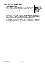
Page 14: ...egrees and the top position sets the footpads to ten 10 degrees INCLINE ADJUSTMENT When the incline is at its lowest position you get a normal elliptical workout As the incline increases you will feel...

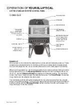
Page 15: ...n the Message Window display will show a software version i e VER 1 0 and the Distance Window will display an odometer reading The odometer shows how many virtual kilometer the elliptical has gone The...

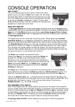
Page 16: ...ncluding how one grips the sensors or how sweaty their hands are The Stop button actually has several functions Pressing the Stop key once during a program will Pause the program for 5 minutes If you...

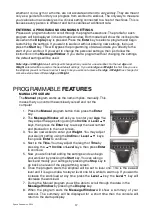
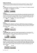
Page 17: ...ess either Age or Weight has changed or someone else enters different Age and Weight PROGRAMMABLEFEATURES MANUAL PROGRAM The Manual program works as the name implies manually This means that you contr...

Page 18: ...signed to increase your cardiovascular function and endurance This is exercise for your heart and lungs It will build up your heart muscle and increase blood flow and lung capacity This is achieved by...

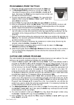
Page 19: ...time then the console will return to the start up display CUSTOM USER DEFINED PROGRAMS The customizable User programs allow you to build and save your own workout You can build your own custom progra...

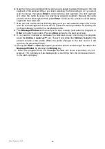
Page 20: ...for building the Incline profile as you did for the resistance profile 8 The Message Window will then tell you to start to begin and save the program or Enter to modify the program Pressing Stop will...

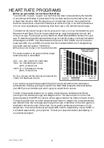
Page 21: ...the zone to stay in for maximum benefit For someone who is 40 years old their target heart rate zone is calculated 220 40 180 maximum heart rate 180 x 6 108 beats per minute 60 of maximum 180 X 8 144...

Page 22: ...erception of Effort 6 Minimal 7 Very very light 8 Very very light 9 Very light 10 Very light 11 Fairly light 12 Comfortable 13 Somewhat hard 14 Somewhat hard 15 Hard 16 Hard 17 Very hard 18 Very hard...

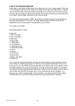
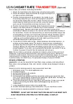
Page 23: ...are skin assures you of proper operation If you wish you may wear the transmitter over a shirt To do so moisten the areas of the shirt that the electrodes will rest upon Note The transmitter is automa...

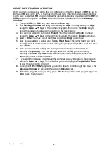
Page 24: ...then press Enter to continue 4 Next is Time You may adjust the Time and press Enter to continue 5 Now you are asked to adjust your Target Heart Rate This is the heart rate level you will strive to rea...

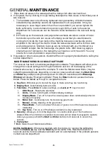
Page 25: ...ou to change the console settings from English to Metric and turn off the beeping of the speaker when a key is pressed for example To enter the Maintenance Menu may be called Engineering Mode dependin...

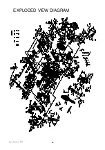
Page 26: ...Dyaco Canada Inc 2013 26 EXPLODED VIEW DIAGRAM...

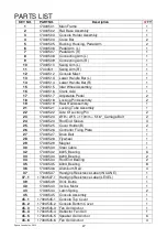
Page 27: ...ube Assembly 1 22 17303522 Axle Of Locking Pin 2 23 17303523 19 15 110mm 5 16 _Carriage Bolt 2 24 17303524 Rod End Sleeve 3 25 17303525 Cover Holder B 2 26 17303526 Controller Fixing Plate 1 27 173035...

Page 28: ...ker Grill Anchor 6 46 17303546 300m m_Connecting Wire Controller 2 47 17303547 850m m_Computer Cable 1 48 17303548 900m m_Connecing Wire Incline Motor Power Cord 1 49 17303549 850m m_Connecting Wire I...

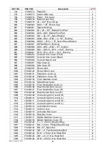
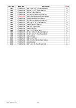
Page 29: ...3035100 Round Disk Cover 2 101 173035101 Pedal Arm Cover L 1 102 173035102 Pedal Arm Cover R 1 103 173035103 Front Stabilizer Cover 1 104 173035104 Slide Wheel Cover 2 105 173035105 Front Handle Bar C...

Page 30: ...147 173035147 5 19m m_Tapping Screw 10 148 173035148 5 16m m_Tapping Screw 9 149 173035149 3 20m m_Tapping Screw 4 150 173035150 M5 20m m_Flat Head Socket Screw 4 151 173035151 3 5 16m m_Tapping Screw...

Page 31: ...Head Screw Driver 1 187 173035187 12 14m m_Wrench 160m m 1 191 173035191 5 16 1 5T_Flat Washer 4 192 173035192 Pedal Tension Spring 2 193 173035193 M8 9T_Nyloc Nut 1 194 173035194 Oval End Cap 2 195...

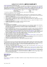
Page 32: ...ot requiring component replacement or treadmill not in ordinary household use 3 Damages caused by services performed by persons other than authorized Dyaco Canada Inc service companies use of parts ot...

Reviews: