background image

5

READ BEFORE UNPACKING YOUR FOLDING TREADMILL

Serious injury could occur if this folding treadmill is not unpacked properly.

There is a Velcro strap installed around the treadmill base that prevents the treadmill from 

unfolding accidentally during shipping. If this strap is not removed properly the treadmill could 

spring open unexpectedly and cause injury if someone is standing near the treadmill when the 

strap is removed.

To ensure your personal safety during removal of the shipping strap please make sure the 

treadmill. Do not turn the treadmill up on its side while removing the shipping strap. This could 

cause the treadmill’s folding mechanism to spring open. If the end of the Velcro strap (that you 

need to grab to remove it) happens to be under the treadmill deck, reach under the deck to 

grab it, but do not tilt the treadmill up to gain access to the strap end.

IMPORTANT SAFETY INSTRUCTIONS

F63 / F65 TREADMILL

Summary of Contents for F63

Page 1: ...PLEASE CAREFULLY READ THIS ENTIRE MANUAL BEFORE OPERATING YOUR NEW TREADMILL F63 F65 TREADMILL OWNER S MANUAL ...

Page 2: ...mation Important Operation Instructions Assembly instructions Folding Instructions Transport Instructions Operation of Your New Treadmill Programmable Features General Maintenance Service Checklist Diagnosis Guide Manufacturer s Limited Warranty 1 2 3 4 8 12 12 13 18 25 28 31 SOLE_F63 F65 Ver A ...

Page 3: ...07 1880 If you purchased this fitness product from Sears they will be your contact for all service needs To contact Sears for any service issues call 1 800 4 MY HOME 1 800 469 4663 Please take a moment at this time to record below the name of the dealer their telephone number and the date of purchase for easy contact in the future We appreciate your confidence in SOLE and we will always remember t...

Page 4: ...ot working properly call your dealer Keep the cord away from heated surfaces Do not operate where aerosol spray products are being used or where oxygen is being administered Sparks from the motor may ignite a highly gaseous environment Never drop or insert any object into any openings Do not use outdoors from the outlet Do not attempt to use your treadmill for any purpose other than for the purpos...

Page 5: ...part is available through most electrical supply stores Examples Grainger part 1D237 or available online at www squared com part QO120HM IMPORTANT ELECTRICALINSTRUCTIONS GROUNDINGINSTRUCTIONS This product must be grounded If the treadmill should malfunction or breakdown ground ing provides a path of least resistance for electric current reducing the risk of electric shock This product is equipped ...

Page 6: ...ing slow acceleration is proper after you have learned to operate the unit Always hold on to a handrail or hand bar while making control changes incline speed etc Do not use excessive pressure on console control keys They are precision set to function or slower If you feel the buttons are not functioning properly with normal pressure contact your SOLE dealer IMPORTANT OPERATIONINSTRUCTIONS IMPORTA...

Page 7: ... if someone is standing near the treadmill when the strap is removed To ensure your personal safety during removal of the shipping strap please make sure the treadmill Do not turn the treadmill up on its side while removing the shipping strap This could cause the treadmill s folding mechanism to spring open If the end of the Velcro strap that you need to grab to remove it happens to be under the t...

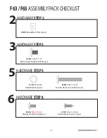
Page 8: ... pcs HARDWARESTEP3 3 130 5 16 x 1 2 Button Head Socket Bolt 8 pcs HARDWARESTEP5 5 113 Ø 10mm Split Washer 4 pcs 139 3 8 x 1 3 4 Button Head Socket Bolt 4 pcs HARDWARESTEP6 6 140 M5 x 15mm Phillips Head Screw 8 pcs 119 3 5 x 12 mm Sheet Metal Screws 4 pcs F63 F65 TREADMILL ...

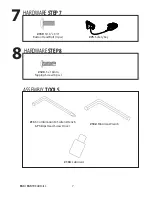
Page 9: ... 5 x 16mm Tapping Screw 6 pcs HARDWARESTEP7 7 159 5 16 x 3 4 Button Head Bolt 4 pcs 75 Safety Key ASSEMBLY TOOLS 131 Combination M5 Allen Wrench Phillips Head Screw Driver 132 M6 Allen Wrench 134 Lubricant F63 F65 TREADMILL ...

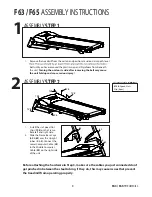
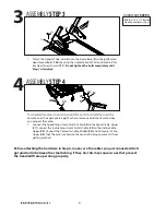
Page 10: ...se left and right side 2 Slide the Frame Base Caps 62 63 over the Upright tubes 4 5 Connect the Lower Computer Cable 49 to the Middle Computer Cable 50 on the right side of the unit ASSEMBLY STEP2 2 HARDWARE STEP 2 128 Speed Nuts Clip 6 pcs F63 F65 ASSEMBLY INSTRUCTIONS Before attaching the hardware in Step 3 make sure the cables you just connected don t get pinched in between the steel tubing If ...

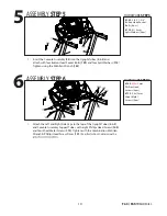
Page 11: ...Adjustment Switch Cable 55 to the Incline Cable Upper 38 Connect the Computer Cable Middle 50 and Computer Cable Upper 48 Tuck the excess cable into the hand rail tubing to prevent it from getting pinched ASSEMBLY STEP4 4 console on at the appropriate height or have someone hold the console while you connect the cables Before attaching the hardware in Step 6 make sure the cables you just connected...

Page 12: ... 4 pcs 113 Ø 10mm Split Washers 4 pcs 1 Attach the Left and Right Side Caps to the top of the Upright Tubes 4 5 and Console Assembly Support Tubes with eight Phillips Head Screws 140 and four Sheet Metal Screws 119 Tighten with the Combination M5 Allen Wrench Phillips Head Screw Driver 131 See illustration to determine the ASSEMBLY STEP6 6 HARDWARE STEP 6 140 M5x15mm Phillips Head Screws 8 pcs 119...

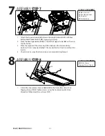
Page 13: ...ll will not function without this in place 4 Check to make sure all bolts and screws are completely tightened ASSEMBLY STEP7 7 HARDWARE STEP 7 159 5 16 x3 4 Button Head Socket Bolts 4 pcs 75 Safety Key 1 Attach the Console mast covers 62 63 to the Frame Base 2 with six Tapping Screws 120 Tighten screws using the Combination M5 Allen Wrench Phillips Head Screw Driver 131 ASSEMBLY STEP8 8 HARDWARE S...

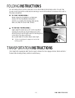
Page 14: ...king telescoping tube assembly in center back of base FOLDING INSTRUCTIONS The treadmill is equipped with four transport wheels that are engaged when the treadmill is folded After folding simply roll the treadmill away TRANSPORTATION INSTRUCTIONS TO UNFOLD THE TREADMILL Apply slight forward pressure on the treadmill running deck with one hand Pull down on the unlocking lever and slowly lower the r...

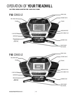
Page 15: ...ART RATE SENSORS SPEAKER INCLINE QUICK KEYS CONTROL KEYS AUDIO IN JACK MP3 CD OR SMARTPHONE SPEEDQUICKKEYS DISPLAY BUTTON DOTMATRIXDISPLAY COOLINGFANS SPEAKER FAN POWER SWITCH HEADPHONE JACK SPEAKER INCLINE QUICK KEYS CONTROL KEYS AUDIO IN JACK MP3 CD OR SMARTPHONE SPEEDQUICKKEYS DISPLAY BUTTON DOTMATRIXDISPLAY CONTACT HEART RATE SENSORS F63 F65 TREADMILL ...

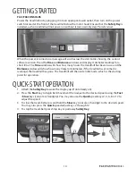
Page 16: ...the Distance window will show how many miles or Kilometers if the treadmill is set to metric readings the treadmill has gone The treadmill will then enter idle mode which is the starting point for operation GETTING STARTED 1 Attach the Safety Key to wake the display up if not already on 2 Press the Start key to begin belt movement then adjust to the desired speed using the Fast Slow keys console o...

Page 17: ...tton is pressed once If the Stop button is pressed a second time the program will end and a workout summary will be displayed If the Stop button is pressed a third time the console will return to the idle mode start up screen If the Stop button is held down for more than 3 seconds the console will reset PAUSE STOP RESET FEATURE Incline may be adjusted anytime after belt movement Press and hold the...

Page 18: ... third time will automatically alternate the Speed and Incline 1 4 MILE TRACK progress The number of laps you complete are accumulated in the lap counter which is below the Pulse window for the F63 and in the Dot matrix window for the F65 PULSE FEATURE The Pulse Heart Rate window will display your current heart rate in beats per minute during the workout You must use both stainless steel sensors o...

Page 19: ...ndicating the console should wake up When the console is asleep the treadmill draws very little power about as much as your 2 switch in the front of the treadmill will completely remove any power 3 To exit the display mode for normal operation press and hold the Stop Enter Display keys for 5 seconds the display will show Display Mode ON Use the speed Up key to change the setting to OFF then press ...

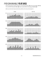
Page 20: ...18 PROGRAMMABLE FEATURES The F63 F65 have ten built in programs one Manual program PO P1 P5 U1 U2 and two Heart Rate Control programs H1 H2 SPEED INCLINE P1 P2 P3 P4 P5 F63 F65 TREADMILL ...

Page 21: ... l i w correct t the calorie count Use the Up Down keys or the Fast Slow to adjust then press enter A note about the Calorie display No exercise machine can give you an exact calorie count because there are too many factors which determine exact calorie burn for a particular person Even if someone is the exact same body weight age and height their Calorie display is to be used as a reference only ...

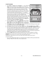
Page 22: ...red under either User 1 or User 2 2 Next the Calorie window F63 or Message window F65 is Age Use the Adjust Up Down keys to adjust Press Enter This is a must to continue even if age is not adjusted 3 The Calorie window F63 or Message window F65 will now be blinking a body weight value Enter your body weight and press Enter 4 The Time window will now be blinking a Time value Adjust the Time and pre...

Page 23: ...0 of maximum 180 X 8 144 beats per minute 80 of maximum So for a 40 year old the training zone would be 108 to 144 beats per minute If you Enter your age during programming the console will perform this calculation automatically Entering your age is used for the Heart Rate control programs After calculating your MHR you can decide upon which goal you would like to pursue heart and lungs and weight...

Page 24: ...is as follows 6 Minimal 7 Very very light 8 Very very light 9 Very light 10 Very light 11 Fairly light 12 Comfortable 13 Somewhat hard 14 Somewhat hard 15 Hard 16 Hard 17 Very hard 18 Very hard 19 Very very hard 20 Maximal You can get an approximate heart rate level for each rating by simply adding a zero to each rating For example a rating of 12 will result in an approximate heart rate of 120 bea...

Page 25: ... you of proper operation If you wish you may wear the transmitter over a shirt To do so moisten the areas of the shirt that the electrodes will rest upon Note The transmitter is automatically activated when it detects activity from the user s heart Additionally it automatically deactivates when it does not receive any activity Although the transmitter is water resistant transmitter after use to pr...

Page 26: ... value Adjusting Age will change the Target HR value 4 The Time window will now be blinking Adjust the time and press enter 5 Now you are asked to adjust the HR1 or H2 value The default is 60 HR1 220 age x 60 or 80 HR2 220 age x 80 You may select a higher or lower number also Adjust the number by pressing the Speed Up or Down keys console or handrails and press Enter to continue 6 key You can also...

Page 27: ...s the problem could actually be the drive belt located under the motor cover that connects the motor to the front roller If that belt is loose it feels similar to the walking belt being loose Tightening the motor belt should be done by a trained service person BELT DECK deck is kept as clean as possible Use a soft damp cloth or paper towel wipe the edge of the belt and the area between the belt ed...

Page 28: ...o the left side then turn the bolt only a 1 4 turn to the right clockwise and wait a few minutes for the belt to adjust itself Continue to make 1 4 turns until the belt stabilizes in the center of the running deck If the belt is too close to the right side turn the bolt counter clockwise The belt may require periodic tracking adjustment depending on use and walking running characteristics Some tre...

Page 29: ... caps enough to get your hand under the belt 5 10 turns Make sure to loosen both bolts the same amount of turns and also the point they were before Once the belt is loose wipe the deck with a clean lint free cloth to remove any dirt Apply the whole tube of lubricant onto the deck surface about 18 inches from the motor cover Squeeze out the contents of the tube across the deck parallel to the motor...

Page 30: ...un calibration 2 If you press start and the belt never moves then the display shows LS contact service Motor is not responsive after pressing start Treadmill will only achieve approximately 7 mph but shows higher speed on display This indicates motor should be receiving power to operate Low AC voltage to treadmill Do not use an extension cord If an extension cord is required it should be as short ...

Page 31: ...h or Metric display readings V Key tone Will turn on or off the speaker to disable the beeping D Security Allows you to lock the keypad so no unauthorized use of the machine is allowed When the child lock is enabled the console will not allow the keypad to operate unless you press and hold the Start and Enter buttons for 3 seconds to unlock the console 1 Press and hold the Start Stop and Enter key...

Page 32: ... key Continue to hold the Start and Slow keys until the SW ver Prompt appears in the message window Release the keys and press the Slow key to enter the menu 3 Use the Fast and Slow keys to scroll through the menu enter key to select and stop key to return to previous a Key tone Turns the speaker on or off so there is no beeping sound ...

Page 33: ... for treadmill not requiring component replacement or treadmill not in ordinary household use 3 Damages caused by services performed by persons other than authorized Maurice Pincoffs Canada service companies use of parts other than original Maurice Pincoffs Canada parts or external causes such as corrosion discoloration of paint or plastic alterations modifications abuse misuse accident improper m...

Page 34: ...4 1016514 Clevis Pin 1 15 1016515 Fastening Bushing 1 16 1016516 Dual Torsion Spring 1 17 1016517 Release Lever 1 18 1016518 ChenChin Torsion Spring 1 19 1016519 Cylinder 1 20 1016520 Drive Belt 1 21 1016521 Front Roller W Pulley 1 21 2 1016521 2 Magnet 2 22 1016522 Rear Roller 1 23 1016523 Running Deck 1 24 1016524 Running Belt 1 25 1016525 PVC Handgrip 2 26 1016526 Handrail Support 1 27 1016527 ...

Page 35: ... 1016547 300mm 764 764_Connecting Wire Black 1 48 1016548 800m m_Computer Cable Upper 1 49 1016549 1150m m_Computer Cable Lower 1 50 1016550 1200m m_Computer Cable Middle 1 52 1016552 Console 1 52 1 1016552 1 Console Top Cover 1 52 2 1016552 2 Console Bottom Cover 1 52 3 1016552 3 INCLINE Key 1 52 4 1016552 4 SPEED Key 1 52 5 1016552 5 Drink Bottle Holder L 1 52 6 1016552 6 Drink Bottle Holder R 1...

Page 36: ... Transparent Piece 1 52 42 1016552 42 Plastic Washer 6 53 1016553 Motor Top Cover 1 54 1016554 300m m_Speed Adjustment Switch W Cable 1 55 1016555 300m m_Incline Adjustment Switch W Cable 1 56 1016556 Cushion 6 57 1016557 Ø75 35L_Transportation Wheel 2 58 1016558 Ø62 Ø32 30L_Transportation Wheel 2 59 1016559 30 60_Square End Cap 2 60 1016560 300m m_Foot Rail 2 61 1016561 690m m_Foot Rail 2 62 1016...

Page 37: ...lt 4 92 1016592 M8 25m m_Flat Head Countersink Bolt 4 93 1016593 M3 10m m_Phillips Head Screw 1 94 1016594 M5 20m m_Phillips Head Screw 1 95 1016595 M8 12m m_Hex Head Bolt 2 96 1016596 5 16 42 m m_Button Head Socket Bolt 1 97 1016597 M5_Nyloc Nut 1 98 1016598 1 2 _Nyloc Nut 4 99 1016599 3 8 _Nyloc Nut 4 100 10165100 5 16 _Nyloc Nut 3 101 10165101 M8_Nyloc Nut 1 102 10165102 3 8 _Nut 3 103 10165103...

Page 38: ...ench Phillips Head Screw Driver 1 132 10165132 M6_Allen Wrench 1 133 10165133 Controller Back Plate 1 134 10165134 Lubricant 1 136 10165136 Handgrip End Cap 2 137 10165137 3 5 32m m_Sheet Metal Screw 8 139 10165139 3 8 1 3 4 _Button Head Socket Bolt 4 140 10165140 M5 15m m_Phillips Head Screw 12 141 10165141 Left Handgrip Side Cap L 1 142 10165142 Left Handgrip Side Cap R 1 143 10165143 Right Hand...

Page 39: ...erage Holder 1 159 10165159 5 16 3 4 _Button Head Socket Bolt 4 160 10165160 M5_Split Washer 4 161 10165161 LOGO Cover L 1 162 10165162 LOGO Cover R 1 171 10165171 Rear Roller Cover L 1 172 10165172 Rear Roller Cover R 1 ...

Page 40: ...38 EXPLODED DIAGRAM F65 ...

Page 41: ...ver 1 18 1016518 ChenChin Torsion Spring 1 19 1016519 Cylinder 1 20 1016520 Drive Belt 1 21 1016521 Front Roller W Pulley 1 21 2 1016521 2 Magnet 2 22 1016522 Rear Roller 1 23 1016523 Running Deck 1 24 1016524 Running Belt 1 25 1016525 PVC Handgrip 2 26 1016526 Handrail Support 1 27 1016527 Steel Cable Tension Spring 1 28 1016528 Wire Clamp 1 29 1016529 Wire Tie Mount 8 30 1016530 Motor Bottom Cov...

Page 42: ...r L 1 52 6 1016552 6 Drink Bottle Holder R 1 52 7 1016552 7 STOP Key 1 52 8 1016552 8 START Key 1 52 14 1016552 14 Front Console Cover Top 1 52 15 1016552 15 Front Console Cover Bottom 1 52 16 1016552 16 300m m_Safety Switch Module W Cable 1 52 17 1016552 17 Fan Assembly 1 52 18 1016552 18 Deflector Fan Grill 1 52 19 1016552 19 Anchor 3 52 20 1016552 20 550m m_Speaker W Cable 1 52 21 1016552 21 20...

Page 43: ...1016567 Right Connecting Cap Bottom 1 68 1016568 Rear Adjustment Base L 1 69 1016569 Rear Adjustment Base R 1 70 1016570 Motor Cover Anchor 5 71 1016571 Ø10 Ø24 3T_Nylon Washer A 2 72 1016572 Ø50 Ø13 3T_Nylon Washer B 4 73 1016573 Adjustment Foot Pad 2 74 1016574 Motor Bracket 1 75 1016575 800m m_Trapezoidal Safety Key 1 76 1016576 Belt Guide 2 77 1016577 Wheel Sleeve 2 80 1016580 1 2 1 1 4 _Carri...

Page 44: ...Washer 2 113 10165113 Ø10_Split Washer 8 114 10165114 M3_Split Washer 1 115 10165115 M5_Star Washer 4 116 10165116 4 12m m_Sheet Metal Screw 20 117 10165117 5 16m m_Tapping Screw 27 118 10165118 5 19m m_Tapping Screw 1 119 10165119 3 5 12m m_Sheet Metal Screw 41 120 10165120 5 16m m_Tapping Screw 19 121 10165121 Ø13 Ø32 2 5T_Flat Washer 2 124 10165124 3 12 m m_Tapping Screw 4 125 10165125 4 50m m_...

Page 45: ...Motor Cover Plate 1 148 10165148 Pedal Cover Top 2 149 10165149 Pedal Cover Bottom 16 151 10165151 1000m m_Ground Wire 1 152 10165152 13m m_Bolt Cap 2 153 10165153 400m m_Audio Cable 1 156 10165156 Drink Bottle 1 157 10165157 3 5 18m m_Sheet Metal Screw 6 158 10165158 Beverage Holder 1 159 10165159 5 16 3 4 _Button Head Socket Bolt 4 160 10165160 M5_Split Washer 4 161 10165161 LOGO Cover L 1 162 1...

Page 46: ...44 EXPLODED DIAGRAM F63 ...

Reviews: