SOLE S.A. – Solar Collectors – Installation Manual
17
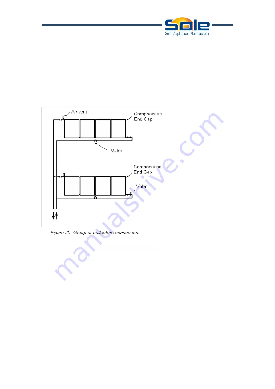
liquid will be done by the top of collector's opposite end of each bank. On the top
connection an end cap must be installed.
The route of the pipeline will be conducted so as to minimize the parts where the flow
of the hot fluid runs (of the collectors towards the tank or to the interchange at the
plant room).
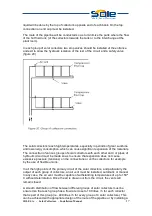
In each group of solar collectors two stop valves should be installed at the entrance
and exit to allow the hydraulic isolation of the rest of the circuit and a safety valve
(figure 20).
The solar collectors reach high temperatures, especially in periods of great sunshine
and low energy consumption, which can cause significant expansion of the materials.
The connection of various groups of solar collectors with each other and / or pipes of
hydraulic circuit must be made so as to ensure that expansion does not cause
excessive pressure (tensions) on the connections or on the collectors, for example
by the use of flexible unions.
In all the high points of the primary circuit of the solar collectors, and particularly the
output of each group of collectors, an air vent must be installed, automatic or manual.
In any case, the air vent must be capable of withstanding temperatures of up to 150 º
C without deterioration. Once the air is drawn out from the circuit, the vents will
remain closed.
A smooth distribution of flow between different groups of solar collectors must be
ensured so that each group has a flow rate close to 100 litres / h for each collector
that is part of this group (i.e. 400 litres / h for every group of 4 solar collectors). This
can be achieved with appropriate design of the route of the pipeline or by installing a

