background image

Customer Service 1-888-707-1880

29

Dyaco Canada Inc. 2016

Email: customerservice@dyaco.ca

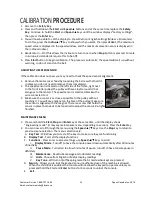
CALIBRATION

PROCEDURE

1.

Remove the

Safety Key

.

2.

P

ress and hold down the

Start

and

Speed

buttons and at the same time replace the

Safety

Key

. Continue to hold the

Start

and

Speed

keys until the window displays “Factory settings”,

then press the

Enter

key.

3. You will now be able to set the display to show Metric or English settings (Miles vs. Kilometers).

To do this, press the

incline

/

key to show which you want, then press

Enter

. (The maximum

speed value is displayed in the speed window, and the maximum elevation value is displayed in

the incline window.)

4. Grade return – On (This allows the incline to return to zero when

Stop

button is pressed. For sale

in Europe, EU standards require this to be off)

5. Press

Start

button to begin calibration. The process is automatic; the speed will start up without

warning, so do not stand on the belt.

ADJUSTING THE SPEED SENSOR

If the calibration does not pass you may need to check the speed sensor alignment.
1. Remove the motor cover hood by loosening the 4 screws that hold it

in place (you do not need to remove them completely).

2. The speed sensor is located on the left side of the frame, right next

to the front roller pulley (the pulley will have a belt around it that

also goes to the motor). The speed sensor is small and black with a

wire connected to it.

3. Make sure the sensor is as close as possible to the pulley without

touching it. You will see a magnet on the face of the pulley; make sure

the sensor is aligned with the magnet. There is a screw that holds the

sensor in place that needs to be loosened to adjust the sensor. Re-tighten the screw when

finished.

MAINTENANCE MENU

1. Press and hold the

Start, Stop

and

Enter

key at the same time, until the display shows

“Engineering mode” (it may say maintenance menu, depending on version). Press the

Enter

key.

2. You can now scroll through the menu using the

Speed

/

keys. Use the

Stop

key to return to

previous menu selection. The menu selections are:

A.

Key Test

- Will allow you to test all the keys to make sure they are functioning

B.

Display Test

- Tests all the display functions

C.

Functions

- Press Enter to access settings, use

Speed

/

keys to scroll

I.

Display Mode

- Turn off to have the console power down automatically after 30 minutes

of inactivity

II.

Pause Mode

- Turned on to allow 5 minutes of pause, turn off to have console pause in

definitely

III.

Maintenance

- Reset lube message and odometer readings

IV.

Units

- Choose from English or Metric display readings

V.

Key Tone

- Will turn on/off beeping noise that is made when keys are pressed.

D.

Securit

y - Allows you to lock the keypad so no unauthorized use of the machine is allowed.

When the child lock is enabled, the console will not allow the keypad to operate unless you

press and hold the Start and

Enter

buttons for 3 seconds to unlock the console.

E.

Exit

Summary of Contents for 16008600630

Page 1: ...OWNER S MANUAL Model 16008600630 PLEASE CAREFULLY READ THIS ENTIRE MANUAL BEFORE OPERATING YOUR NEW TREADMILL...

Page 2: ...t Operation Instructions 4 Assembly Pack Checklist 6 Assembly Instructions 8 Folding Instructions 12 Operation of Your Treadmill 13 Bluetooth Connectivity 17 Programmable Features 18 General Maintenan...

Page 3: ...act Dyaco Canada Inc at 1 888 707 1880 Please take a moment at this time to record below the name of the dealer their telephone number and the date of purchase for easy contact in the future We apprec...

Page 4: ...admill is not working properly call your dealer Keep the cord away from heated surfaces Do not operate where aerosol spray products are being used or where oxygen is being administered Sparks from the...

Page 5: ...ct This is a condition we as a manufacture have no ability to control This part is available through most electrical supply stores Examples Grainger part 1D237 or available online at www squared com p...

Page 6: ...ding on the belt during slow acceleration is proper after you have learned to op rate the unit Always hold on to a handrail or hand bar while making control changes incline speed etc Do not use excess...

Page 7: ...al safety during removal of the shipping strap please make sure the treadmill is positioned flat on the ground in the orientation it would be in if you were using the treadmill Do not turn the treadmi...

Page 8: ...ca ASSEMBLY PACK CHECKLIST HARDWARE STEP 2 HARDWARE STEP 3 HARDWARE STEP 5 HARDWARE STEP 6 2 128 M5 Speed Nuts Clip 6 pcs 3 130 5 16 1 2 Button Head Socket Bolt 8 pcs 5 113 10 2T Split Washer 4 pcs 6...

Page 9: ...016 Email customerservice dyaco ca HARDWARE STEP 7 HARDWARE STEP 8 ASSEMBLY TOOLS 8 120 5 16mm Tapping Screw 6 pcs 7 159 5 16 3 4 Button Head Socket Bolt 4 pcs 75 Safety Key 131 Combination M5 Allen W...

Page 10: ...fold up and cause serious injury ASSEMBLY STEP 2 1 Install the six Speed Nut Clips 128 on the Frame Base left and right side 2 Slide the lower handlebar covers 64 65 onto the console masts notice ori...

Page 11: ...ate height or have someone hold the console while you connect the cables 1 Connect the Speed Adjustment Switch Cable 54 to the Speed Cable Upper 37 Connect the Incline Adjustment Switch Cable 55 to th...

Page 12: ...Split Washers 113 Tighten using the M6 L Allen Wrench 132 ASSEMBLY STEP 6 1 Attach the Left 64 and Right 65 Lower Handlebar Covers to the top of the Upright Tubes 4 5 with six Sheet Metal Screws 175...

Page 13: ...nd Stop buttons if it isn t already attached The treadmill will not function without this in place 4 Check to make sure all bolts and screws are completely tightened ASSEMBLY STEP 8 1 Finish tightenin...

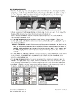
Page 14: ...he treadmill running deck until it is secured by the locking telescoping tube assembly in center back of base TO UNFOLD THE TREADMILL Apply slight forward pressure on the treadmill running deck with o...

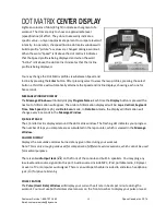
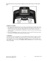
Page 15: ...bly step 7 for reference When the power is turned on a message will scroll across the Message Window showing the current software version Then the Time and Distance windows will display Odometer read...

Page 16: ...The Time Distance and Calorie readings will hold while the unit is in the pause mode After 5 minutes the display will reset and return to the start up screen 2 To resume your exercise when in Pause m...

Page 17: ...time the Display button is pressed the next set of information will appear The order of information displayed will be Laps Vertical Segment Time Max Speed in mph and Data Scan mode In Data Scan mode...

Page 18: ...up When the console is asleep the treadmill draws very little power about as much as your television when it is turned off 2 Removing the Safety Key is similar to entering sleep mode Turning off the...

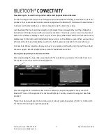
Page 19: ...witch back and forth from the workout display view to internet social media email sites via icons on the display screen When your workout is finished the data is automatically saved to the built in pe...

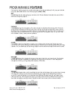
Page 20: ...o program is designed to increase your cardiovascular function and endurance This is exercise for your heart and lungs It will build up your heart muscle and increase blood flow and lung capacity This...

Page 21: ...e or Speed keys to adjust then press Enter Calorie Display Note No exercise machine can give you an exact calorie count because there are too many factors which determine exact calorie burn for a part...

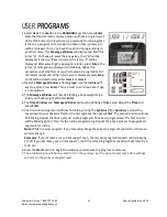
Page 22: ...a must to continue even if age is not adjusted 3 The Message Window will now be blinking a body weight value Enter your body weight and press Enter 4 The Time Window and Message Window will now be bl...

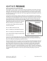
Page 23: ...tem This 60 to 80 is the zone to stay in for maximum benefit For someone who is 40 years old their target heart rate zone is calculated 220 40 180 maximum heart rate 180 x 6 108 beats per minute 60 of...

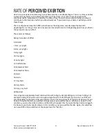
Page 24: ...The scale is as follows Rating Perception of Effort 6 Minimal 7 Very very light 8 Very very light 9 Very light 10 Very light 11 Fairly light 12 Comfortable 13 Somewhat hard 14 Somewhat hard 15 Hard 16...

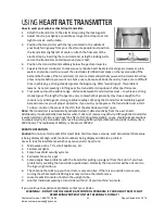
Page 25: ...mediately against bare skin assures you of proper operation If you wish you may wear the transmitter over a shirt To do so moisten the areas of the shirt that the electrodes will rest upon Note The tr...

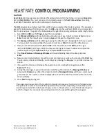
Page 26: ...ou are asked to adjust the HR1 or HR2 value The default is 60 HR1 220 age x 60 or 80 HR2 220 age x 80 You may select a higher or lower number also Adjust the number by pressing the Speed keys and pres...

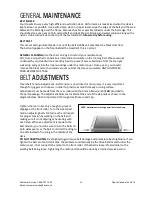
Page 27: ...the black motor hood and vacuum out dirt that may accumulate UNPLUG POWER CORD BEFORE THIS TASK BELT ADJUSTMENTS Tread belt Tension Adjustment Belt tension is not critical for most users It is very im...

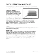
Page 28: ...acking adjustment depending on use and walking running characteristics Some users may affect tracking differently Expect to make adjustments as required to center the tread belt Adjustments will becom...

Page 29: ...lights every 90 hours of use or if you notice that the deck is dry It is recommended that you reach between the belt and deck to verify there is lubricate procedure below even though the Lube indicato...

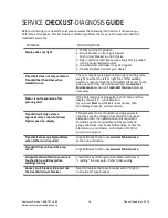
Page 30: ...elt Tension Adjust as necessary Motor is not responsive after pressing start If the belt moves but stops after a short time and the display shows E1 run calibration If you press Start and the belt nev...

Page 31: ...all and black with a wire connected to it 3 Make sure the sensor is as close as possible to the pulley without touching it You will see a magnet on the face of the pulley make sure the sensor is align...

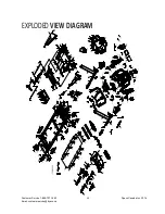
Page 32: ...Customer Service 1 888 707 1880 30 Dyaco Canada Inc 2016 Email customerservice dyaco ca EXPLODED VIEW DIAGRAM...

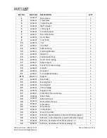
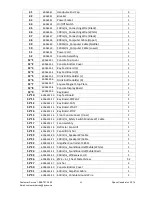
Page 33: ...1 17 6006317 Release Lever 1 18 6006318 ChenChin Torsion Spring 1 19 6006319 Cylinder 1 20 6006320 Drive Belt 1 21 6006321 Front Roller W Pulley 1 21 2 6006321 2 Magnet 2 22 6006322 Rear Roller 1 23 6...

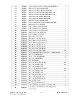
Page 34: ...Magnet Stop Plate 2 52 8 6006352 8 Console Display Board 1 52 9 6006352 9 Key Board 1 52 10 6006352 10 Key fast Board 2 52 11 6006352 11 Key Board DISPLAY 1 52 12 6006352 12 Key Board FAN 1 52 13 600...

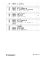
Page 35: ...ning Belt Foot Rail 2 61 6006361 740L_Running Belt Foot Rail 2 62 6006362 Frame Base Cover L 1 63 6006363 Frame Base Cover R 1 64 6006364 Lower Handlebar Cover L 1 65 6006365 Lower Handlebar Cover R 1...

Page 36: ...0063104 8 35 1 5T_Flat Washer 2 105 60063105 25 10 2 0T_Flat Washer 4 106 60063106 10 19 1 5T_Flat Washer 4 107 60063107 5 10 1 0T_Flat Washer 2 108 60063108 8 18 1 5T_Flat Washer 1 109 60063109 5 13...

Page 37: ...145 60063145 Cushion Spacer 2 147 60063147 Top Motor Cover Plate 1 148 60063148 Pedal Cover Top 2 149 60063149 Pedal Inner Cover 16 151 60063151 1000m m_Ground Wire 1 153 60063153 400m m_Audio Cable...

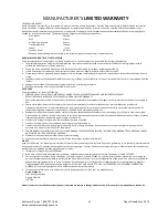
Page 38: ...warranty period for units that are beyond the service call reimbursement period for treadmill not requiring component replacement or treadmill not in ordinary household use 3 Damages caused by servic...

Page 39: ...tion about our other brands and products manufactured and distributed by Dyaco Canada Inc www spiritfitnesscanada ca www dyaco ca www spiritfitnesscanada ca www dyaco ca www solefitness ca www dyaco c...

Page 40: ...Customer Service 1 888 707 1880 38 Dyaco Canada Inc 2016 Email customerservice dyaco ca...

Reviews: