14
customerservice@dyaco.ca
Dyaco
Canada
Inc.
2017
4
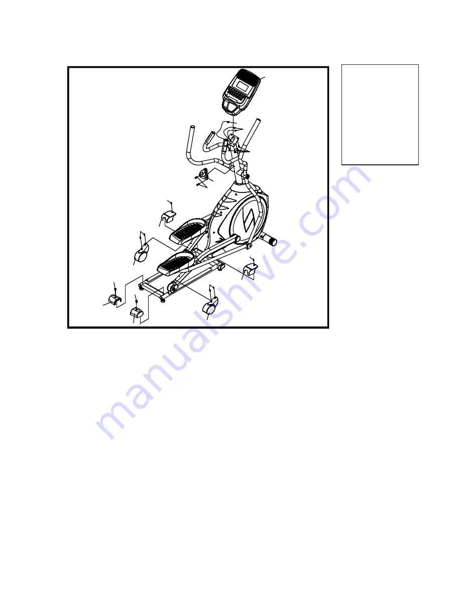
PLASTIC
COVERS
Note:
Use
the
M5
Allen
Wrench/Phillips
Head
Screw
Driver
(
108
)
to
tighten
hardware
in
this
step.
1.
Locate
the
Console
Assembly
(
31
)
and
the
four
Phillips
Head
Screws
(
78
).
There
will
be
two
electrical
wire
connectors
at
the
top
opening
of
the
Console
Mast
(
10
),
two
Hand
pulse
wires
(
37
),
one
Computer
Cable
(
32
).
Connect
these
to
the
mating
connectors
on
the
back
of
the
Console
Assembly
(
31
).
The
connectors
are
keyed
so
you
cannot
plug
them
in
the
wrong
way
so
do
not
force
them.
2.
Storing
the
excess
wire
back
into
the
Console
Mast
(
10
),
carefully
install
the
Console
Assembly
(
31
)
onto
the
mounting
plate
of
Console
Mast
(
10
)
and
secure
using
the
four
Phillips
Head
Screws
(
78
)
3.
Install
the
two
pcs
of
Slide
Wheel
Covers
(
52
)
and
the
four
Phillips
Head
Screws
(
79
)
by
using
the
Phillips
Head
Screwdriver
(
110
).
4.
Use
one
Phillips
Head
Screw
(
79
)
to
secure
Rear
Stabilizer
Cover
(L)
(
61
)
on
the
Pedal
Arm
(L)
and
Rail
Tube
with
Phillips
Head
Screwdriver
(
110
).
Repeat
the
procedure
for
Rear
Stabilizer
Cover
(R)
(
62
)
for
the
other
side.
5.
Use
two
Phillips
Head
Screw
(
79
)
to
secure
Middle
Stabilizer
Cover
(
59
)
on
the
Pedal
Arm
(L.R)
and
Rail
Tube
with
Phillips
Head
Screwdriver
(
110
).
6.
Use
Phillips
head
screw
driver
to
tighten
Drink
Bottle
Holder
(68
‐
2)
on
Console
Mast
tube
with
two
M5
×
12m/m
Phillips
Head
Screws
(68
‐
3)
.
HARDWARE
STEP
4
#78
.
M5
x
10mm
Phillips
Head
Screw
(4
pcs)
#79
.
M5
x
15mm
Phillips
Head
Screw
(8
pcs)
#68
‐
3.
M5
x
12mm
Philips
Head
Screw
(2
pcs)
79
52
62
79
61
79
52
79
79
79
78
32
37
31
59
59
68-3
68-2


