Installation
and
Operation
Manual
(Rev
A)
PVI
50
‐
100KW
Series
Inverters
DOCR
‐
070233
Page
14
of
92
4
DC
Connections
from
the
PV
Array
and
AC
Connections
to
the
Grid
WARNING:
All
electrical
installations
shall
be
performed
in
accordance
with
applicable
local,
state,
and
national
electric
codes.
WARNING:
Only
connect
the
DC
and
AC
power
and
grounding
wires
with
the
AC
and
DC
disconnect
switches
off
and
the
circuits
isolated
from
AC
power
from
the
grid
and
DC
power
from
the
array.
WARNING:
Make
sure
to
connect
the
inverter
and
other
exposed
metal
equipment
in
the
system
to
the
grounding
electrode
system
through
the
installation
of
the
Grounding
Electrode
Conductor(s)
and
Equipment
Grounding
Conductors
before
proceeding
to
connect
any
DC
or
AC
power
wires.
WARNING:
Only
make
AC
connections
directly
to
the
lugs
within
the
AC
disconnect
switch
and
DC
connections
to
the
lugs
within
the
DC
disconnect
switch.
NOTE:
All
grounding
and
power
wiring
terminals
are
dual
rated
for
Copper
and
Aluminum
Wire.
When
using
aluminum
wire
exercise
best
industry
practices
to
ensure
a
reliable
connection;
thoroughly
clean
the
conductor
just
prior
to
making
the
electrical
connection
and
use
an
oxide
inhibitor
to
prevent
the
formation
of
aluminum
oxide.
NOTE:
Grounding
and
power
wiring
terminals
are
rated
to
167°F
(75
ᵒ
C).
NOTE:
When
conduit
hubs
are
used
for
DC
and
AC
cable
entry
in
an
outdoor
or
wet
location,
rain
‐
tight
or
wet
location
hubs
that
comply
with
the
requirements
in
the
Standard
For
Fittings
For
Conduit
and
Outlet
Boxes,
UL514B,
are
to
be
used.
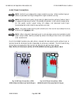
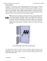
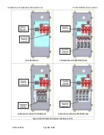
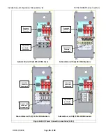
AC
grounding
and
power
connections
are
made
in
the
AC
disconnect
switch
of
the
inverter.
The
type
of
AC
disconnect
switch
provided
with
the
inverter
depends
on
the
inverter
power
rating,
output
voltage,
and
fusing
specified
by
the
customer
(i.e.
fused
or
unfused).
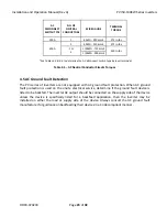
DC
grounding
and
power
connections
are
made
in
the
DC
disconnect
switch
of
the
inverter.
The
type
of
DC
disconnect
switch
provided
with
the
inverter
depends
on
the
inverter
power
rating
and
DC
overcurrent
protection
specified
by
the
customer
(i.e.
fuses
or
breakers,
amperage,
and
quantity).
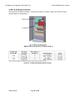
4.1
Grounding
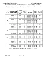
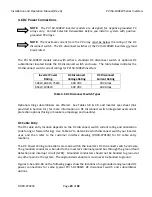
The
PVI
50
‐
100KW
inverter
has
grounding
connection
points
in
the
DC
and
AC
disconnect
switches
as
listed
below.
These
points
are
used
for
Grounding
Electrode
Conductor
(GEC)
and
Equipment
Grounding
Conductor
(EGC)
connections.
PV
systems
have
EGC
and
GEC
conductor
requirements


