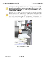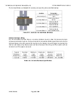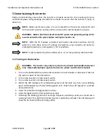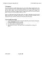
Installation
and
Operation
Manual
(Rev
A)
PVI
50
‐
100KW
Series
Inverters
DOCR
‐
070233
Page
18
of
92
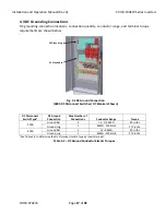
4.4
AC
Power
Connections
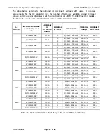
NOTE:
Each
AC
lug
is
designed
for
single
conductor
use
only.
Where
multiple
lugs
per
phase
are
provided,
each
lug
is
designed
for
single
conductor
use
only.
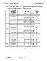
NOTE:
Note
that
each
inverter
power
rating
is
offered
with
the
option
of
either
a
fused
or
unfused
AC
disconnect
switch.
The
installer
should
refer
to
the
current
requirements
for
the
specific
inverter
power
rating,
AC
voltage,
and
disconnect
switch
type
(fused/unfused)
to
determine
the
appropriate
wire
sizes.
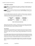
NOTE:
The
phase
rotation
of
the
grid
connections
to
the
inverter
must
follow
the
L1/A,
L2/B
and
L3/C
clockwise
order.
NOTE:
When
a
fused
AC
disconnect
switch
is
not
provided,
overcurrent
protection
of
AC
power
output
cables
shall
be
provided
by
others
according
to
local,
state,
and
national
code
requirements.
The
PVI
50
‐
100KW
models
come
with
either
a
standard
AC
disconnect
switch
without
fuses
or
optional
fused
AC
disconnect
switch
(depending
on
what
was
ordered).
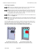
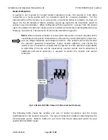
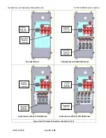
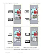
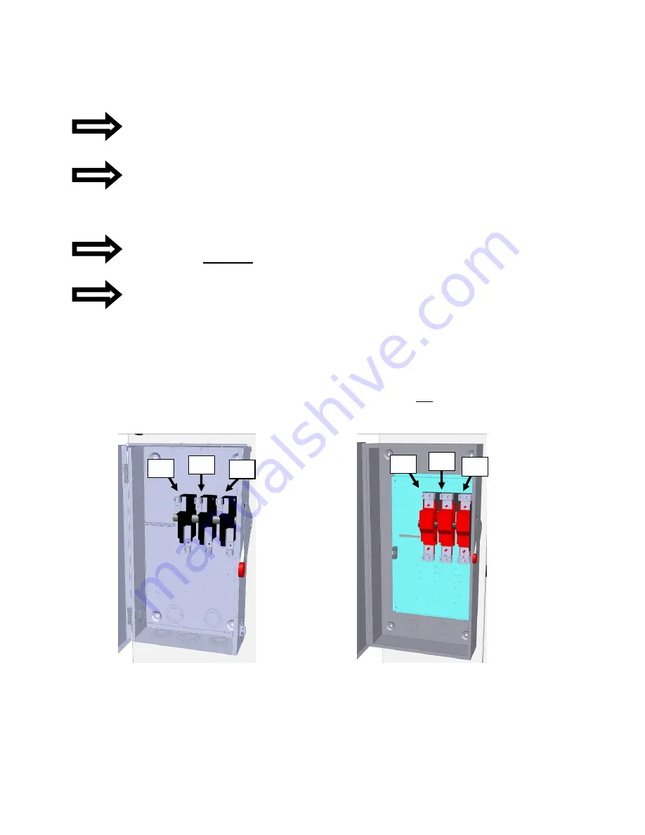
The
AC
Power
Wiring
connections
are
made
within
the
inverter’s
AC
disconnect
switch
as
shown
below.
Note
that
the
AC
disconnect
switches
of
PVI
50
‐
100KW
inverters
are
load
break
rated.
Fig.
4.3
AC
Power
Connections
‐
200A
(200A
Unfused
AC
Disconnect
Switch
Shown)
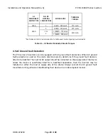
Fig.
4.4
AC
Power
Connections
‐
400A
(400A
Unfused
AC
Disconnect
Switch
Shown)
L1
L2
L3
L1
L2
L3


