Installation
and
Operation
Manual
(Rev
A)
PVI
50
‐
100KW
Series
Inverters
DOCR
‐
070233
Page
28
of
92
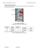
DC
Breaker
Subcombiner
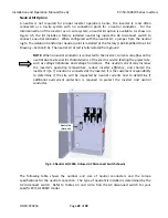
The
table
below
includes
requirements
for
the
DC
conductor
size,
the
number
of
terminals
available
and
proper
terminal
torque
for
the
fused
DC
subcombiner
options
on
the
PVI
50
‐
100KW.
NOTE:
The
torque
is
different
for
the
grounded
and
ungrounded
terminals
on
the
DC
breaker
subcombiner.
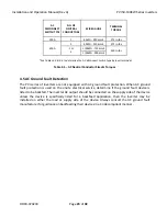
BREAKER
CURRENT
RATING
BREAKER
QUANTITY
NO.
OF
TERMINALS
(per
Breaker)
WIRE
GAUGE
TERMINAL
TORQUE
(GROUNDED)
TERMINAL
TORQUE
(UNGROUNDED)
40A,
50A,
60A,
70A,
80A,
90A,
100A
2
‐
8
1
8AWG
‐
1/0AWG
275
in
‐
lbs
45
in
‐
lbs
110A,
125A,
150A,
175A,
200A
2,
3,
4
1
2AWG
‐
300kcmil
275
in
‐
lbs
275
in
‐
lbs
225A,
250A,
300A
2
1
4/0AWG
‐
350kcmil
275
in
‐
lbs
275
in
‐
lbs
2
2/0AWG
‐
250kcmil
275
in
‐
lbs
375
in
‐
lbs
Table
4.9
Fused
DC
Subcombiner
Conductor
Size
and
Torques
4.7
DC
Ground
Fault
Detection
and
Interruption
The
inverter
is
equipped
with
an
automatic
DC
Ground
Fault
Detection
and
Interruption
(GFDI)
circuit.
When
a
single
ground
fault
exceeding
the
ground
fault
fuse
pickup
value
is
present
in
the
PV
array
or
in
the
DC
wiring
to
the
inverter,
the
DC
GDFI
fuse
will
blow
and
a
ground
fault
will
be
signaled
by
means
of
a
yellow
LED
and
a
message
on
the
front
LCD
display.
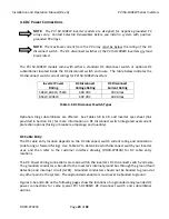
DC
Ground
Fault
Current
Pickup
PVI
50KW
PVI
60KW
PVI
75KW
PVI
85KW
PVI
100KW
2
Amps
(PN:
Bussmann
KLM
‐
2,
2A
DC,
600
VDC
rated)
REPLACE
ONLY
WITH
SAME
MAKE/MODEL
Table
4.10
–
DC
GFDI
Specifications
WARNING:
In
the
event
of
a
ground
fault,
DO
NOT
TOUCH
any
equipment
(including,
but
not
limited
to:
the
inverter,
the
PV
array
disconnect
switch,
the
PV
array
combiners,
the
PV
panels,
the
PV
racking
system).
Immediately
contact
the
installer
or
another
qualified
person
to
locate
and
repair
the
source
of
the
ground
fault.
Be
aware
that
normally
grounded
conductors
and
equipment
may
be
energized
and
may
pose
a
significant
shock
and
/
or
fire
hazard.


