Installation
and
Operation
Manual
(Rev
A)
PVI
50
‐
100KW
Series
Inverters
DOCR
‐
070233
Page
31
of
92
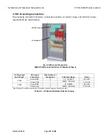
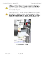
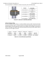
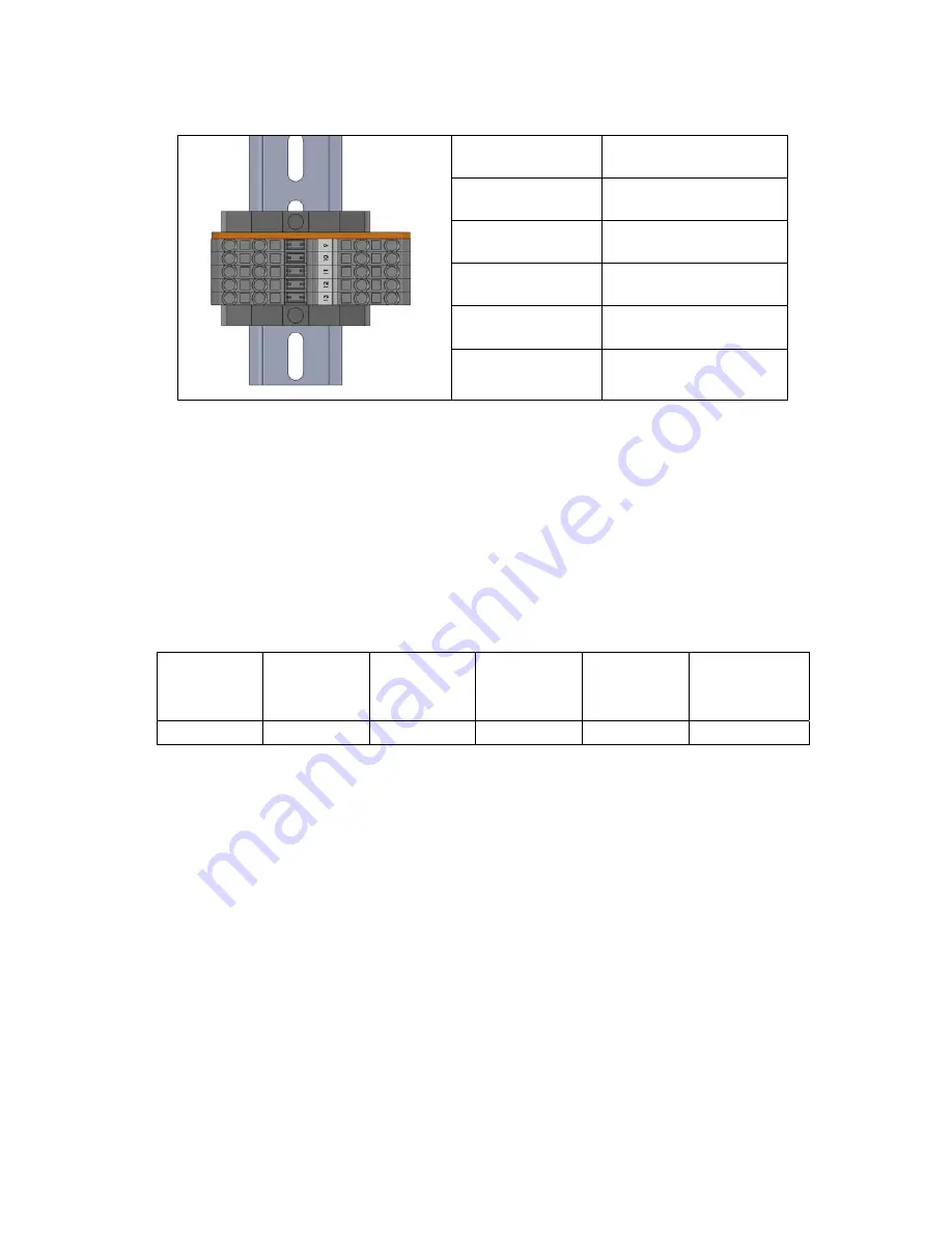
The
terminal
blocks
are
labeled
9
‐
13
and
are
wired
per
the
picture
and
table
below:
Location
Connection
Terminal
Block
9
Remote
Shutdown
Input
Terminal
Block
10
Remote
Shutdown
Return
Terminal
Block
11
Revenue
Grade
Meter
(RS485A)
Terminal
Block
12
Revenue
Grade
Meter
(RS485B)
Terminal
Block
13
Revenue
Grade
Meter
(RS485
‐
Gnd)
Table
4.11
–
Customer
Terminal
Block
Definition
Remote
Shutdown
Wiring
The
PVI
50
‐
100KW
inverters
feature
a
remote
shutdown
input
to
allow
for
advanced
remote
command
and
control
systems.
The
input
required
is
an
isolated
24VDC
signal
that
is
wired
to
the
terminal
blocks
on
the
left
panel
of
the
inverter
by
the
installer.
Once
the
signal
is
activated,
the
inverter
will
slowly
ramp
down
power
and
then
disconnect
from
the
grid.
The
inverter
will
not
reconnect
until
the
signal
is
removed.
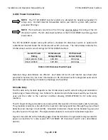
Typical
Shutdown
Ramp
Time
Nominal
Input
Voltage
Minimum
Input
Voltage
Maximum
Input
Voltage
Minimum
Current
Capability
Terminal
Wire
Size
1
second
24VDC
21.6VDC
26.4VDC
100mADC
26
–
14AWG
Table
4.12
–
Remote
Shutdown
Specifications

