background image

Installation and Operation Manual (Rev B)    


19 


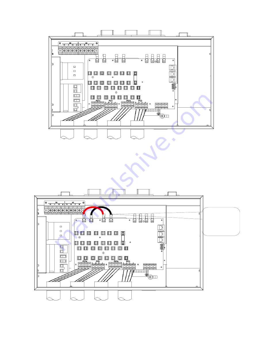
Figure 5.2 Diagram of Wire Connections For Use With Dual MPPT Zone 


The two MPPT zones can be combined by using the following configuration as shown in Figure 

5.3.  Jumper wire between J1 & J3 for positive terminals, jumper second wire between J2 & J4 for 

negative terminals.  


Figure 5.3 Diagram of Wire Connections For Use With One Combined MPPT Zone 

-1 MPPT 

working 

alone. 

Summary of Contents for PVI 14TL

Page 1: ...1 PVI 14TL PVI 20TL INSTALLATION AND OPERATION MANUAL Revision B 2014 Solectria Renewables LLC YOUR K dZ Z E t DIS SOLIGENT 800 967 6917 www soligent net ...

Page 2: ... Manual Rev B 2 IMPORTANT REGISTRATION AND WARRANTY INFORMATION For warranty to become active this inverter must be registered To activate warranty and register inverter please visit the link below www solectria com registration ...

Page 3: ...al shock and to ensure the safe installation and operation of the inverter the following safety symbols are used to indicate dangerous conditions and important safety instructions WARNING This indicates a fact or feature very important for the safety of the user and or which can cause serious hardware damage if not applied appropriately Use extreme caution when performing this task NOTE This indic...

Page 4: ...PTIONS DE SECURITE IMPORTANTES Tous les travaux d installation électrique doivent être exécutés en conformité aux normes électriques locales ainsi qu à la norme nationale américaine et canadienne Le PVI ne contient aucune pièce requérant un entretient effectué par l utilisateur Pour toute maintenance veuillez consulter Solectria Renewables ou un installateur agrée par Solectria Renewables les coor...

Page 5: ...rnal Monitoring 24 7 1 SolrenView Logger Installation If not pre ordered from the factory 25 7 2 One Gateway Several Inverters 27 7 3 Communication Connection 27 7 6 Establishing Ethernet Connectivity 29 7 7 Setting up TCP IP Networking 30 Manually Configuring Network Settings 31 Automatically Configuring Network Settings 32 Setting Fallback IP Address 32 7 8 Enabling SolrenView Web based Monitori...

Page 6: ...n Policy 53 12 Technical Data 55 12 1 Output AC Specifications 55 12 2 Other Specifications 55 12 3 Input DC PV Specifications 56 12 4 Temperature Derating Curve 56 12 5 Internal Circuit Diagram 56 13 Appendices 57 Appendix A PVI 14TL 20TL datasheet 57 Appendix B String Sizing Tool 57 Appendix C Contact Information 57 Appendix D Authorized Distributors 57 Appendix E UL1741 IEEE 1547 CSA22 2 107 1 ...

Page 7: ... commercial industrial institutional or electrical utility facility s electrical system which is connected to the electrical grid If the PV system and inverter are providing the same amount of electrical power that the facility is using then no power is taken from or fed into the utility grid If the facility is using more power than the PV system is providing then the utility grid provides the bal...

Page 8: ...indicators used to signal the operating status of the inverter Conduit Knockouts From left to right DC inputs and equipment ground 4 AC output ground terminals 1 Signal port 1 A Spare to be used as needed 1 DC disconnect Switch Built in lockable disconnect switch used to disconnect the DC input to the inverter AC disconnect Switch Built in lockable disconnect switch used to disconnect the AC outpu...

Page 9: ...here are four LED indicators used to signal the operating status of the inverter Conduit Knockouts From left to right DC inputs and equipment ground 4 AC output ground terminals 1 Signal port 1 A Spare to be used as needed 1 Combined AC and DC disconnect Switch Built in lockable disconnect switch used to disconnect the DC input from the array and the AC output from the grid Main housing does not c...

Page 10: ...Installation and Operation Manual Rev B 10 21 42in 41 6in 8 46in 544mm 1058mm 215mm Figure 1 4 PVI 14TL PVI 20TL Inverter Dimensions ...

Page 11: ...e the inverter can be mounted outdoors The maximum life for the inverter can be achieved by mounting the unit in a clean dry and cool location For optimal electrical system efficiency use the shortest possible AC and DC cables and use the maximum allowable cable size Install the inverter in an accessible location following local electric codes for enclosure proximity to other equipment Although th...

Page 12: ...tility vault or electrical closet the air circulation must be sufficient for heat dissipation Provide external ventilation to maintain an ambient condition of 50o C or less for full power The ambient temperature should be kept as low as possible at all times for optimal inverter operation and life 3 Inverter Mounting WARNING Any lifting or moving of the inverter requires at least two people Moving...

Page 13: ... follow these lifting guidelines may cause structural damage to the inverter and void the warranty WARNING Do not install the inverter on or over combustible surfaces or materials WARNING Severe injury or death could occur if the inverter mounting fails and falls on a person NOTE The weight of the inverter will exert an added load to the wall or area where mounted Be sure to verify proper load cap...

Page 14: ...imum distances that must be met are shown in Figure 3 3 There should be a minimum of 12 inches of space available on both sides In the case of two or more inverters are installed side by side then there should be minimum of 24 inches available between inverters for adequate access and cooling There should be a minimum of 24 inches of space available from the bottom of the inverter ...

Page 15: ...the handles in order to lift the inverter safely At least two people are required to lift the inverter Return side covers when mounting is complete Figure 3 4 Inverter Wall Bracket Mounting Drill 6 holes with a 13 32 inch drill bit and install expansion bolts available in accessory box Secure the bracket to the wall using six 5 16 X 25 screws as shown in Figure 3 4 ...

Page 16: ...rter installation as shown in Figure 3 5 Figure 3 6 Mounting Inverter on Wall Bracket Install the inverter on the wall bracket and make sure that the top and bottom hooks of the inverter are engaged with the bracket as shown in Figure 3 6 Reinstall side cover on the inverter using four M4 x 12 screws Torque 10 in lb ...

Page 17: ... below Position Connection entry A Knockout holes for DC input wires and equipment ground B Knockout hole for AC output and ground wires C Knockout hole for communication wires D Spare knockout hole that can be used according to the customer s needs Figure 4 1 DC input equipment ground PVI 14TL and PVI 20TL inverters have a ground bar with four terminals used to terminate the equipment ground Torq...

Page 18: ...re wiring Verify correct polarity and voltage before installing fuses WARNING Before connecting the DC conductors of the PV array to the inverter fuse terminal or bypass them verify that the DC voltage is less than 600Vdc in all conditions DC voltages over 600V will damage the inverter Configure the array such that the open circuit voltage will never exceeds 600 Vdc Warranty is voided if more than...

Page 19: ...PT Zone The two MPPT zones can be combined by using the following configuration as shown in Figure 5 3 Jumper wire between J1 J3 for positive terminals jumper second wire between J2 J4 for negative terminals Figure 5 3 Diagram of Wire Connections For Use With One Combined MPPT Zone 1 MPPT working alone ...

Page 20: ...er as showed in table 5 2 below Warning DC fuses must be removed before any of the configurations in table 5 2 are allowed Warning Fusing at the combiner box prior of the connecting to the inverter is required for all of the connections in table 5 2 DC wiring connection point Configuration Max DC Wire Size Conductors Torque ALL DC terminal block 4 8 inputs Standard use of integrated string combine...

Page 21: ...1 IN1 IN2 IN2 PV1 PV2 PV2 1 2 3 4 P1 1 2 3 4 P2 1 2 3 4 P3 1 2 3 4 P4 8 AWG 2 Inputs 1 MPPT Zone PV1 Inverter IN1 IN1 IN2 IN2 PV1 PV2 PV2 1 2 3 4 P1 1 2 3 4 P2 1 2 3 4 P3 1 2 3 4 P4 8 AWG 1 Input 1 MPPT Zone PV1 Inverter IN1 IN1 IN2 IN2 PV1 1 2 3 4 P1 1 2 3 4 P2 1 2 3 4 P3 1 2 3 4 P4 4 AWG Table 5 2 Internal String Combiner Bypass Options ...

Page 22: ...educe voltage drop Inverter Model AC Voltage Typical Number of AC Conductors Minimum AC Wire Size Maximum AC Wire Size Torque Maximum Continuous Output Current Recommended Min Interconnection Breaker Fuse Size PVI 14TL 208VAC 4 1 per phase plus neutral 10 AWG 90 C Cu 8 AWG 90 C Cu 10 In lb 39 A 50 A PVI 20TL 480VAC 4 1 per phase plus neutral 10 AWG 90 C Cu 8 AWG 90 C Cu 10 In lb 27 3 A 35 A Table ...

Page 23: ...al jumper wire connected to GND at the inverter Compatible with 14TL Compatible with 20TL 3 Wire Delta 3 phase Delta Neutral jumper wire connected to GND at the inverter Compatible with 14TL Compatible with 20TL Other Configurations All other configurations not mentioned in this document such as Phase Corner Grounded Delta Not compatible with 14TL Not compatible with 20TL Table 6 2 Allowable AC in...

Page 24: ...rface HMI This HMI consists of the LCD display and four buttons Figure 7 1 SolrenView Gateway HMI WARNING SolrenView gateway connections must be made by qualified personnel only To reduce the risk of electric shock you should never attempt to open the inverter DC or AC enclosure doors or perform any service or troubleshooting without prior training Before attempting to service or troubleshoot the ...

Page 25: ...sk of electric shock you should never attempt to open the inverter DC or AC enclosure doors or perform any service or troubleshooting without prior training Before attempting to service or troubleshoot the inverter please read the entire manual 1 Locate the location where the SolrenView Gateway to be installed Figure 7 2 SolrenView Gateway Mounting Location in wiring box Figure 7 3 Mounting Locati...

Page 26: ...y The connector is keyed so it cannot be installed incorrectly Connectors are as follows 3 Connect the green connector end of the SolrenView Monitoring Harness to the 5 pin socket on the Subcombiner PCB board at location P1004 4 Mount the SolrenView Gateway into the mounting location orientating the gateway as shown below Torque to 8 in lbs Figure 7 3 SolrenView Gateway Installed into Subcombiner ...

Page 27: ...hernet jack on the logger installed in either the first or the last inverter to router or switch for connection to the customer s broadband internet service Figure 7 4 Multiple Inverters Single SolrenView unit 7 3 Communication Connection There are two RS485 signal ports on the inverter labeled RS485 1 and RS485 2 The wires are labeled 1 to 8 from left to right as shown in below Table 7 1 Wiring r...

Page 28: ...STOP or START the inverter from the Main Display UP To scroll up within the individual menu items To increase a data value DOWN To scroll down within the individual menu items To decrease a data value ENTER To enter into the selected menu To begin to edit a data value To accept a data value Figure 7 5 Main Display During normal inverter operation the Main Display shows AC Energy Eac and AC Power P...

Page 29: ...ion as indicated by the arrow Press the ENTER button to activate the selected function or submenu 7 6 Establishing Ethernet Connectivity Before SolrenView web based monitoring can function the inverter must be networked to the Internet To connect the inverter to the network 1 Locate the Ethernet port on the bottom of the SolrenView gateway 2 Install a CAT5 CAT5e or CAT6 networking cable between th...

Page 30: ...to setup TCP IP as this is done in the factory prior to shipping the inverter Viewing Current TCP IP settings 1 Select the Info function on the Main Menu and the press ENTER button 2 Information on the inverter will be displayed including the IP gateway and netmask settings Press the ENTER button to hold the display on the item of interest In the above example the IP address gateway and netmask va...

Page 31: ...lect the DHCP function then press ENTER to edit the setting 4 Press the DOWN button to turn DHCP Mode Off then press ENTER to save this setting The DHCP Mode setting will now show OFF 5 Press the DOWN button to access the Static IP setting 6 Press ENTER to modify the Static IP value 7 Specify each of the four octet values 0 255 one at a time Press the UP button to increment the octet Press the DOW...

Page 32: ...t the DHCP function and press ENTER to edit this setting 4 Press the DOWN button to turn DHCP Mode On and press ENTER to save this setting The DHCP Mode setting will now show ON Setting Fallback IP Address When the SolrenView gateway is set to use DHCP but is unable to acquire an IP address lease it will fallback to using a specified IP address after a few seconds To specify a fallback IP 1 Select...

Page 33: ... gateway from the DHCP server select the Autodetect option in using the HMI Autodetect is the special gateway value of 0 0 0 0 11 To configure the SolrenView gateway to use a manual gateway specify each of the four octet values 0 255 one at a time Press the UP button to increment the octet Press the DOWN button to decrement the octet Press the ENTER button to accept the octet Press the ESCAPE butt...

Page 34: ...ll be lost so it is important to establish Internet connectivity soon after the inverters are commissioned NOTE If a third party monitoring service is installed SRV mode should be set to off NOTE Enabling SRV Mode when the SolrenView com data monitoring service has not been purchased will result in unnecessary wear and tear on the SolrenView gateway To enable SolrenView com data monitoring 1 Selec...

Page 35: ...f the time can be changed with the buttons Press the UP button to increment the hour and the DOWN button to decrement the hour Press the ENTER button to accept the hour value Press the ESCAPE button to cancel and return to the menu Minutes and Seconds can be set in a similar manner 7 10 Rebooting the SolrenView Gateway If the SolrenView Gateway cannot communicate over the Internet or is not updati...

Page 36: ... option from the menu then press ENTER 3 A message warning that the SolrenView gateway is about to be set to factory defaults will be shown Press the ESCAPE button to cancel the reset 4 Select the Yes option under Clear settings to reset the SolrenView gateway to factory defaults The Reset Storage screen will appear for a moment 7 12 HMI Menu Structure ...

Page 37: ...ith the PV modules connected and inverter disconnect switches still off perform a final check of the PV voltage and polarity once more using a digital volt meter and probing the positive and negative PV connections Turning on the Inverter Turn on the dedicated three phase circuit breaker or disconnect switch at the building service For PVI 14TL turn on AC disconnect first followed by the DC discon...

Page 38: ...dicators on the front of the inverter provide valuable operating information 9 1 LCD Figure 9 1 LCD Figure 9 2 Key Descriptions Key Description Definition of function Escape key Back end mute Enter key Confirm entering the menu confirm set point Up Page up in selection menu Down Page down in selection menu Left 1 when setting parameters Right 1 when setting parameters ...

Page 39: ... Power output Pac AC Power Output KW Run Time RunT Hours AC1 Voltage Vab AC Voltage V AC2 Voltage Vbc AC Voltage V AC3 Voltage Vca AC Voltage V AC Freq Freq AC Frequency Hz AC1 Current Ia AC Current A AC2 Current Ib AC Current A AC3 Current Ic AC Current A Heatsink Temperature T_int C Ambient Temperature T_ambient C DC Voltage Vpv1 DC Voltage V DC Current Ipv1 DC Current A DC Voltage Vpv2 DC Volta...

Page 40: ...formation can be found in the menu 1 Up to 100 entries of most recent fault messages are recorded and retrieved 2 The latest 21 days operation history data is available 3 Product software hardware and serial number information 4 Cumulative generated power information 3 History 1 ErrHist 2 Recent Data 3 Version 4 Etot NoError 1 St2010 12 15 20 50 SPI CommError 2 Ed2010 12 15 20 59 IntProtect1 No Ye...

Page 41: ...y 1 ErrHist 2 Recent Data 3 Version 4 Etot NoError 1 St2010 12 15 20 50 SPI CommError 2 Ed2010 12 15 20 59 IntProtect1 No Yes Enter day offset 2 ß 12 15 RunT h Energy KW Pmax KWh Mach Ver Serial Number Etot KWh Figure 9 4 1 History Menu and Submenu 20TL ...

Page 42: ... 15 21 14 ON OFF ON 1 中文 2 English KeyBeep Enabled AlarmBeep Disabled Address 2 BaudRate 1 1 9600 2 19200 1 Enable 2 Cycle min 60 3 Manual ARC Operation Enable ARC Clear CleraErr Figure 9 5 1 System setup menu and submenu 14TL 4 Setting 1 Power ON OFF 2 Language 3 Sounds 4 SysTime 5 Commun 2009 12 15 21 14 ON OFF ON State 中文 English English Ver KeyBeep Enable AlarmBeep Disabled Address 2 BaudRate ...

Page 43: ...Not enough DC power to turn on the inverters internal circuitry Example No sun condition RUN Indicates the operating state of the inverter LED on Inverter is generating power Blinking Derated running state LED on 0 5s LED off 1 5s LED off Inverter is not generating power GRID Indicates the state of the electric grid LED on AC Grid is within limits Blinking AC Grid not within limits LED on 0 5s LED...

Page 44: ...e Inverter back on 4 If error does not clear contact Solectria Customer Service Alarm 2 SPICommErr Inverters internal communication failure 1 Poor connection of the inverters internal communication connector 1 Observe for 5 minutes and see whether the alarm is cleared automatically 2 Switch off the inverters internal disconnects 3 Switch the Inverter back on 4 If error does not clear contact Solec...

Page 45: ...ters internal memory 1 Observe for 5 minutes and see whether the alarm is cleared automatically 2 If error does not clear contact Solectria Customer Service Protection 1 OverTemp Ambient temperature or temperature inside inverter is too high 1 Ambient temperature outside the inverter is too high 1 Confirm that external ambient temperature is within the specified range of operating temperature 2 Ve...

Page 46: ...d voltage frequency is abnormal 1 Grid frequency is out of range 1 Observe for 10 minutes and see whether the alarm is cleared automatically 2 Verify grid frequency is within range 2 Loose AC connections 3 Verify proper AC wiring 4 If error does not clear Contact Solectria Customer Service Protection 4 PV1 2 VoltOver DC input voltage exceeds the specified value 1 DC over voltage 1 Observe for 30 m...

Page 47: ...l grounding conditions 2 Contact System installer to check installation for possible Ground Fault 3 If error does not clear contact Solectria Customer Service Protection 7 IntProtectA Z Internal problem within the inverter 1 One of the inverters internal protection features was triggered causing the inverter to shut down 1 Observe for 10 minutes and see whether the alarm is cleared automatically 2...

Page 48: ... Renewables and cover defects in workmanship and materials Solectria Renewables price for the products is based on inclusion of these limited warranty provisions and disclaimers In the event of a conflict between the terms of this Limited Warranty and any terms and conditions proposed by purchasers of Solectria Renewables products these Limited Warranty provisions shall govern the parties obligati...

Page 49: ... further details on other products Standard or Extended Limited Warranty Coverage Solectria Renewables will at its sole option repair or replace the defective product free of charge provided that Solectria Renewables is notified of the product defect within the Warranty Period for the product and provided that Solectria Renewables through inspection establishes the existence of such a defect and t...

Page 50: ...ontiguous United States and Canada For Alaska Hawaii and all other installation locations Solectria Renewables will cover the cost of return shipment of product one way from the customer The warranty does not include customs fees broker fees or other taxes that may be imposed by the government agency The warranty does not cover travel and or labor necessary to repair the product Obtaining Service ...

Page 51: ...nally or damaged from improper use or use in an unsuitable environment b The product if it has been subjected to fire water generalized corrosion biological infestations acts of God or input voltage that creates operating conditions beyond the maximum or minimum limits listed in the Solectria Renewables product specifications including high input voltage from generators or lightning strikes c The ...

Page 52: ... AFFILIATES BE LIABLE FOR ANY SPECIAL DIRECT INDIRECT INCIDENTAL OR CONSEQUENTIAL DAMAGES LOSSES COSTS OR EXPENSES HOWEVER ARISING WHETHER IN CONTRACT OR TORT INCLUDING WITHOUT RESTRICTION ANY ECONOMIC LOSSES OF ANY KIND ANY LOSS OR DAMAGE TO PROPERTY INCLUDING LOSS OF USE AND INTANGIBLE HARM OF ANY KIND AND ANY PHYSICAL DAMAGE OR OTHER DAMAGE ARISING FROM OR AS A RESULT OF ANY USE MISUSE OR ABUSE...

Page 53: ...on Before returning a product directly to Solectria Renewables you must obtain a Return Material Authorization RMA number and the correct factory Ship To address Products must also be shipped prepaid Product shipments will be refused and returned at your expense if they are unauthorized returned without an RMA number clearly marked on the outside of the shipping box if they are shipped collect or ...

Page 54: ...f description of the problem Ship the unit prepaid to the address provided by your Solectria Renewables customer service representative Returning a product from outside of the USA or Canada In addition to the above you MUST include return freight funds and are fully responsible for all documents duties tariffs and deposits ...

Page 55: ...Output Voltage 208 480 VAC Operating AC Voltage range 88 110 VAC Operating frequency 59 3 60 5 Hz Power Factor Unity 0 99 Total Harmonic Distortion THD 3 Continuous Output Power 14 20 kW Continuous Output Current 39 27 3 Amps Table 12 1 AC Output Specifications PVI 14TL PVI 20TL Peak Efficiency 96 7 97 40 CEC Weighted Efficiency 96 97 Table 12 2 Efficiency of Inverters 12 2 Other Specifications In...

Page 56: ... per Zone 30 35 Amps Table 12 4 DC Input Specifications 12 4 Temperature Derating Curve 12 5 Internal Circuit Diagram The basic power flow within the PVI 14TL 20TL series of inverters is below Note that the GFDI circuit is not depicted EMI Filter INV EMI Filter L1 L2 L3 N PE Filter Surge Protector DC_Switch PV1 PV1 DC DC EMI Filter PV2 PV2 DC DC AC_Switch Surge Protector Surge Protector Figure 12 ...

Page 57: ...tact Information Solectria Renewables LLC 360 Merrimack Street Building 9 2nd floor Lawrence Massachusetts 01843 USA Tel 978 683 9700 Fax 978 683 9702 Sales general info inverters solectria com Customer Support service solrectria com Website www solren com Appendix D Authorized Distributors See website for complete and updated listing http www solren com distributors Appendix E UL1741 IEEE 1547 CS...

Page 58: ...Installation and Operation Manual Rev B 58 ...

Reviews: