PVI 3000S, 4000S, 5000S, 5300 Series Inverters
Installation and Operation Manual (Rev A)
24
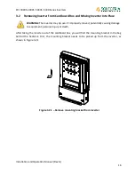
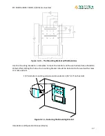
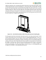
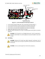
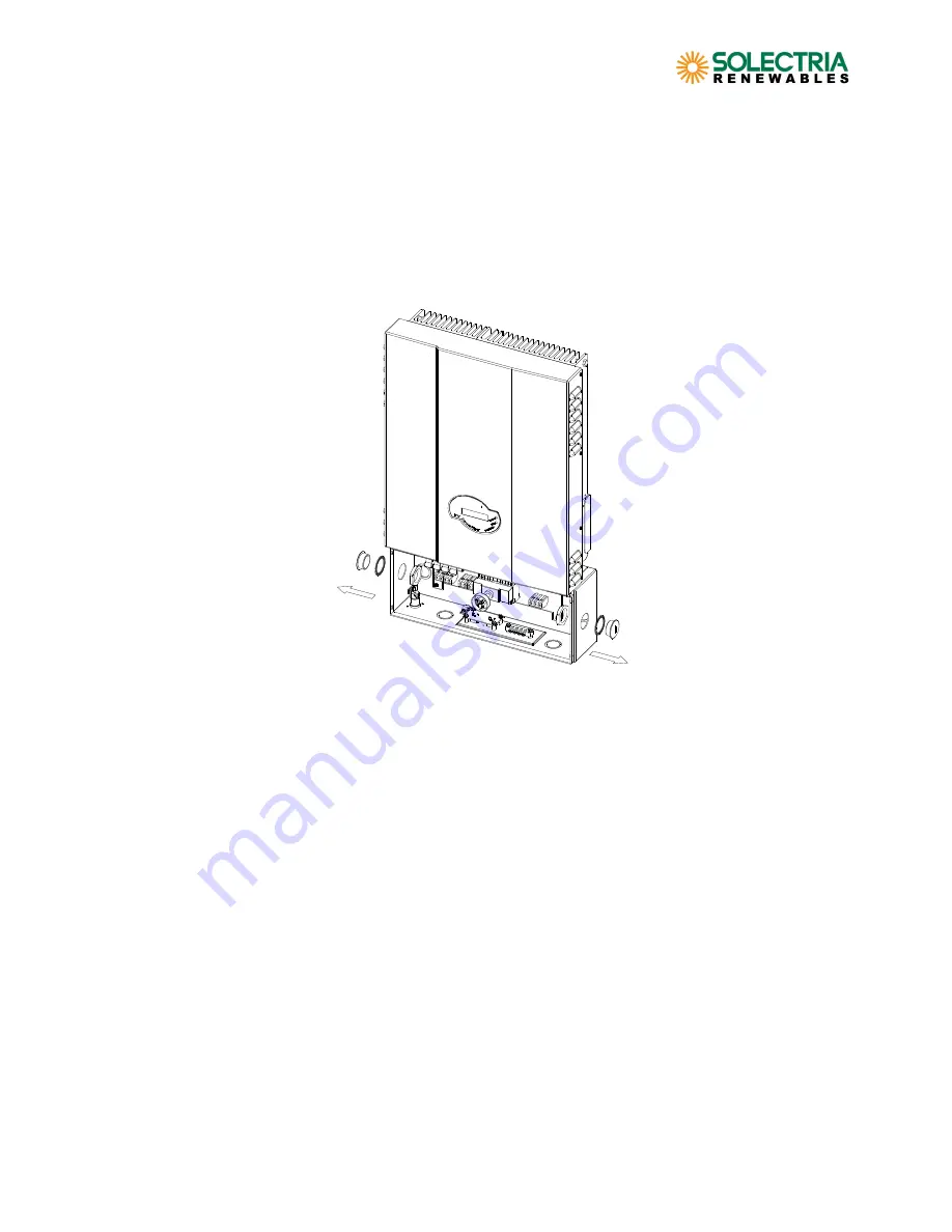
After the wiring box cover is removed, the conduit hole covers can be removed (or KOs in other
locations punched out) as shown in the Figure 4.1.3, for the DC and AC conduits which will enter
and exit these locations. Holes are pre-punched (and shipped with hole covers) for 1” conduit
fittings on the left and right sides of the wiring box, these holes are centered at 2.5” from the wall
mounting surface. ¾” and 1” concentric KOs are on the bottom of the AC and DC sides of the
wiring box and these are located 2.63” from the wall mounting surface. ¾” and 1” concentric KOs
are on the back of the AC and DC sides of the wiring box for routing wiring out the back of the
box into the wall for a “hidden wiring” installation.
Figure 4.1.3 – Punch Out the Knockouts where the Conduits will enter the Wiring Box.
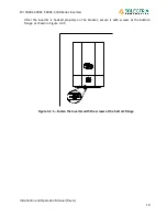
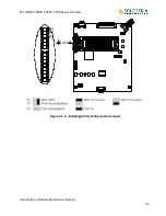
The following three sections describe the wiring for the AC, DC, and communication ports. The AC
and DC wiring shall be done in the wiring box of the PVI 3000S/4000S/5000S/5300. There are a
pair of DC terminal blocks, a DC fuse, a bypass terminal block, two (2) RJ-45 connectors, and one
(1) AC terminal block in the wiring box as shown in the Figure 4.1.4. The DC terminal blocks are
used to connect up to 4 PV strings that will parallel connected in the wiring box (3 strings for the
PVI 3000S), or the fuse bypass terminal can be used if the fused combiner feature is not needed.
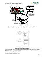
The RJ-45 connectors are used for external communication to a remote computer or
communication gateway. The AC terminal block is used to connect to the building/utility grid
through a circuit breaker in the building distribution panel.


