PVI 3000S, 4000S, 5000S, 5300 Series Inverters
Installation and Operation Manual (Rev A)
25
AC Terminal Block
PV String Fuse
Ground Bar
GFDI Fuse
RJ45-R
RJ45-L
P
o
s
itv
ie
g
ro
u
n
d
N
e
g
a
tiv
e
g
ro
u
n
d
1
1
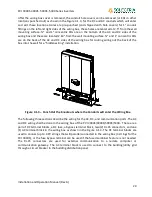
Figure 4.1.4 - Wiring Box (Front and Bottom View).
Before wiring the PVI 3000S-5300 inverter, the installer must determine the grid connection/
utility configuration that the inverter will be connected to. The PVI 3000S-5300 inverter is default
set for utility interconnection with a neutral connection. However, it may be reconfigured for a
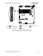
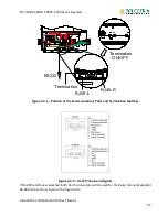
connection without a neutral. The utility configuration jumpers, J210, are located on the control
board as shown in Figure 4.1.5 are used to set the PVI 3000S-5300 inverter to be connected to
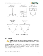
the commonly used utility configuration
types shown in Figure 4.1.6. As shown in Figure 4.1.5,
the P1 and P2 pins are used to configure the PVI 3000S-5300 inverter for the connection types of
208V and 240V AC outputs with or without neutral. When the inverter is set for the connection
configurations with neutral, it can automatically distinguish the utility voltage and adjust the
output AC voltage according the grid voltage. When connecting the PVI 3000S-5300 inverter to
the building / utility, the voltage
must
be compatible.
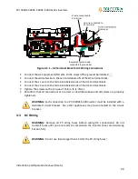
Fuse bypass terminal(s)


