PVI 3000S, 4000S, 5000S, 5300 Series Inverters
Installation and Operation Manual (Rev A)
31
WARNING:
Polarities of each DC input voltage from a PV string shall be connected
correctly to the “+” (positive) and “–” (negative) terminals of a pair respectively.
The DC voltage must be less than 600V in any condition.
WARNING:
The inverter is listed for no backfeed current into the PV array.
However, the ampacity of the PV strings must be calculated when determining
proper PV combiner fuse value to prevent fire hazard.
•
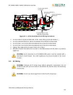
The positive (+) wire of the DC input shall be connected to the terminal labeled
“Ungrounded (+)” and the negative (-) wire of the DC input shall be connected to the
terminal labeled “Grounded (-)”, except when using positively grounded modules. In that
case, see Appendix D at the end of this manual for further instruction.
•
Wire nuts shall not be used to join any wires together or to make any connections
anywhere in the PV system except where acceptable by code. Wire nuts are a frequent
cause of unreliable connections, resistive connections, and ground faults and are not
allowed in certain applications by NEC.
•
Connect the equipment ground wire to the screw of the ground bar labeled .
•
Tighten the screws with a torque of 15.6 in-lb (1.7Nm).
WARNING:
Route the DC wires to the PVI 3000S-5300 inverters away from any
possible hazards that could damage to the wires (such as sharp corners, edges or
near covers where wires could be pinched or crushed).
Bypassing Fused Combiner
If no (fused) combiner is required, as in the case of using a fused combiner other than the fused
combiner inside the inverter, then the “Ungrounded (+)” bypass terminals (2) to the right of fuses
can be used, as shown in Figure 4.3.2. Up to 2 PV circuits can be connected. The “Grounded (-)”
connections are still to be connected to the “Grounded (-)” terminal block.
4.4
Connection of Communication Wiring
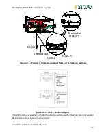
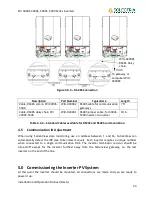
The PVI 3000S-5300 inverter supports RS-485 which is used to communicate to the remote
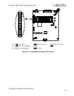
computer or communication gateway. As shown in Figure 4.4.1, there are two RJ-45 connectors,
RJ45-R and RJ45-L that are located on the bottom of the wiring box. The pin numbers of the RJ-
45 connectors and the corresponding signals are described in Figure 4.4.2 below. If the RS485 is
used as the external communication interface and the inverter is the last device in the RS485
loop, then the termination switch shall be put to ON position (shown in Figure 4.4.3). The
installer needs to open the front cover of the wiring box to switch the termination switch to ON
position. The termination switch is default set to OFF position.

