PVI 3000S, 4000S, 5000S, 5300 Series Inverters
Installation and Operation Manual (Rev A)
38
3 seconds ↓
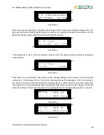
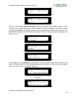
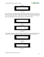
Then three (3) seconds later, it displays the setting of the nominal grid voltage configuration. The
grid type setting of 208/240 with neutral is used as the display example shown below. For the
grid type setting, please refer to Section 4 Wiring the Inverter.
3 seconds ↓
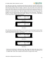
If the grid type is set to 240 Vac without neutral, then the display will be looked as the figure
shown below.
3 seconds ↓
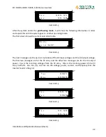
Then three (3) seconds later, LCD will show the voltage setting for the inverter to drop the grid
connection. The settings of the Vl-nH and its clearing time will be displayed. The Vl-nH setting is
the phase-to-neutral (rms) high threshold voltage setting at which point the inverter disconnects
its output from the AC power grid when abnormally high phase-to-neutral AC voltage is detected.
After the setting of the Vl-nH is displayed, the setting of the Vl-nL will be displayed for 3 seconds.
3 seconds ↓
3 seconds ↓
V
l
-
n
L
X
X
X
.
X
V
C
l
r
t
<
X
X
X
C
y
c
s
V
l
-
n
H
X
X
X
.
X
V
C
l
r
t
<
X
X
X
C
y
c
s
G
r
i
d
T
y
p
e
L
1
-
L
2
2
4
0
V
G
r
i
d
T
y
p
e
L
1
1
2
0
V
L
2
1
2
0
V
S
/
N
X
X
X
X
X
X
X
X
X
X
X
X
B
R
X
X
X
X
X
I
D
X
X
X

