PVI 3000S, 4000S, 5000S, 5300 Series Inverters
Installation and Operation Manual (Rev A)
39
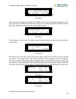
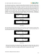
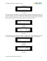
Then three (3) seconds later, it displays the setting of the VacH which is the phase-to-phase (rms)
high threshold voltage setting at which point the inverter disconnects itself from the grid when
abnormally high phase-to-phase AC voltage is detected. Also, the setting of the clearing time
which is the total duration of time to disconnect the output from the AC grid is displayed. The
clearing time is the summation of the de-bounce time and the hardware delay time. This delay is
necessary to avoid nuisance trips. After the settings of the VacH and its clearing time, the
settings of the VacL and its clearing time will be displayed for three (3) seconds. The display Vl-
nH/Vl-nL is only for 208/240 with neutral setting, VacH/VasL is only for 240 or 208 without
neutral, they would not display at the same time.
3 seconds ↓
3 seconds ↓
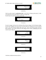
Then the high and low threshold settings of the AC frequency and the clearing time will be shown
for three (3) seconds. When the AC frequency reaches the high or low threshold setting, the
inverter will disconnect its output from the AC grid.
3 seconds ↓
3 seconds ↓
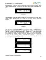
Then the LCD will display the setting of the AC high voltage limit above which value, inverter
will reduce the output power until the AC voltage drops within this setting. If the grid type is set
to 208/240 with neutral, then the display will be looked as the figure shown below.
F
a
c
L
X
X
.
X
X
H
z
C
l
r
t
<
X
X
X
C
y
c
s
F
a
c
H
X
X
.
X
X
H
z
C
l
r
t
<
X
X
X
C
y
c
s
V
a
c
L
X
X
X
.
X
V
C
l
r
t
<
X
X
X
C
y
c
s
V
a
c
H
X
X
X
.
X
V
C
l
r
t
<
X
X
X
C
y
c
s


