PVI 3000S, 4000S, 5000S, 5300 Series Inverters
Installation and Operation Manual (Rev A)
65
•
Ensure that the inverter is off and de-energized from both AC and DC sides.
•
Open the wiring box and inverter cover.
•
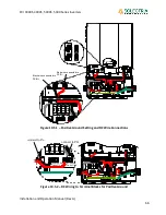
As shown in Figure 10.5.1, the JP14 and JP15 jumpers need to be placed at the
higher positions to set to positive grounding.
•
The red DC wire, that connects the inverter board to the wiring box, needs to be
connected to “Grounded” DCIN- terminal on the Inverter board.
•
The black wire, that connects the inverter to the wiring box, needs to be
connected to “Ungrounded” DCIN+ terminal on the Inverter board.
•
Disconnect the black DC wires (from PV array) connected to “GROUNDED
CONDUCTOR” terminal block.
•
Disconnect the red DC wires (from PV array) connected to “UNGROUNDED
CONDUCTOR” terminal block.
o
If using the bypass terminals, disconnect the wires from the associated
terminal block.
•
Connect the black DC wires (from PV array) to the “UNGROUNDED CONDUCTOR”
terminal.
o
If using the bypass terminals, connect the black DC wires to this set of
terminals.
•
Connect the red DC wires (from PV array) to the “GROUNDED CONDUCTOR”
terminal.
•
Add permanent weatherproof labels over the Ungrounded (+) and Grounded (-)
labels below the green terminal blocks. The left terminal block must be labeled
“Ungrounded (-)“ and the right terminal block must be labeled “Grounded (+)”.
Optional: add “Warning, Positively Grounded Unit” label to outside of unit at
bottom right corner of wiring box. (a label kit is available from Solectria if
requested).
•
Tighten the set screws to a torque of 1.7Nm (15.6 in-lb.))


