PVI 3000S, 4000S, 5000S, 5300 Series Inverters
Installation and Operation Manual (Rev A)
66
1
N
e
g
a
tiv
e
g
ro
u
n
d
P
o
s
itv
ie
g
ro
u
n
d
1
JP14
J
P
1
4
JP15
J
P
1
5
P
o
s
it
vi
e
g
ro
u
n
d
N
e
g
a
tiv
e
g
ro
u
n
d
1
1
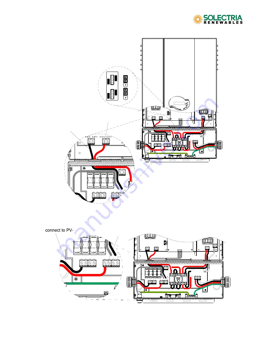
Black wire connected to
DCIN+
Red wire connected to
DCIN-
Figure 10.5.1 – Positive Ground Setting and DC Wire Connections
P
o
s
itv
ie
g
ro
u
n
d
N
e
g
a
tiv
e
g
ro
u
n
d
1
1
connect to PV+
UNGROUNDED
CONDUCTOR
GROUNDED
CONDUCTOR
Figure 10.5.2 – DC Wiring to Terminal Blocks for Positive Ground

