Installation
and
Operation
Manual
(REV
H)
PVI
6500
/
PVI
7500
14
98.43
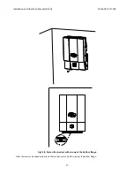
Fig
2.2.4
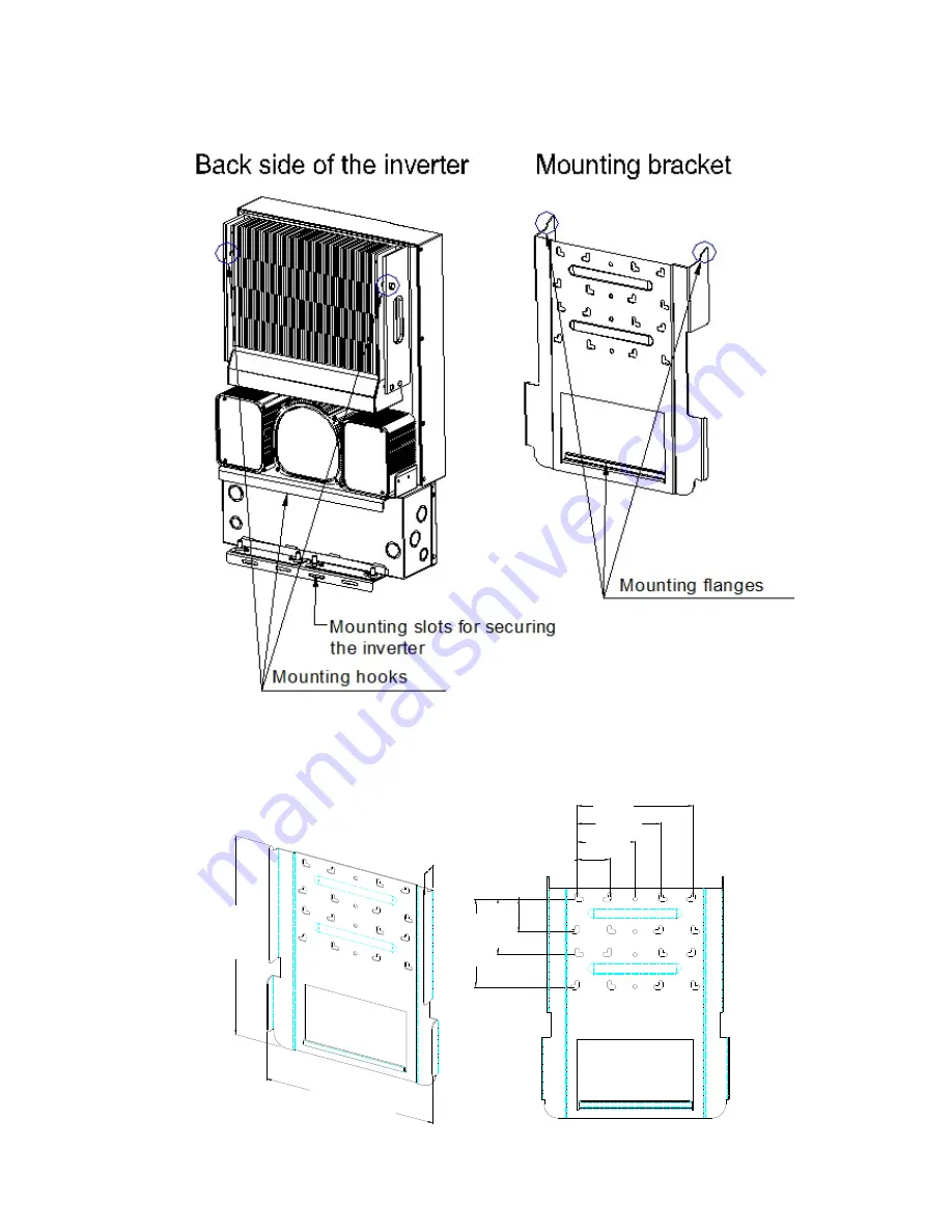
Remove
the
bracket
from
the
inverter
1.
Use
the
bracket
(Fig
2.2.5)
as
a
template
to
mark
the
hole
locations
on
the
wall.
After
drilling
the
holes,
the
mounting
bracket
should
be
fastened
to
the
wall
with
screws
or
screw
‐
anchors
as
shown
in
Figure
2.2.6.
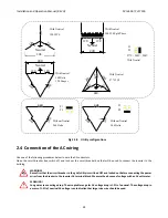
405mm
525
mm
44
mm
70mm
125mm
180mm
250mm
7
0mm
1
20mm
190m
m
2.75
7.5”
4.94”
7.12”
2.75”
4.75”
2.91”
20.67”
9.88”
16.94”


