Installation
and
Operation
Manual
(REV
H)
PVI
6500
/
PVI
7500
20
AC
Over
Current
Protection
Device:
A
dedicated
AC
over
current
protection
device
is
required
for
each
PV
inverter.
Every
PVI
requires
a
208V,
240V
or
277V
AC
rated
2–pole
over
current
protection
device.
The
following
is
a
table
showing
the
appropriate
over
current
protection
device
rating
for
the
PVI
6500
and
7500
at
different
service
voltages.
AC
Voltage
PVI
6500
PVI
7500
208VAC
40A
50A
240VAC
35A
40A
277VAC
30A
35A
AC
and
DC
Disconnects:
The
integral
AC
&
DC
disconnects
are
standard
features
of
the
PVI
6500
‐
7500
inverters.
The
PV
system
may
need
additional
AC
or
DC
disconnect
if
required
by
the
utility
or
local
code.
Connecting
the
AC
Inverter
Wiring:
WARNING:
The
wiring
of
the
PV
inverter’s
AC
and
DC
connections
must
only
be
done
with
the
building
AC
circuit
breaker
off
and
locked
out
and
the
PV
array
disconnected
or
covered
with
an
opaque
material
(or
other
method
that
establishes
electrically
safe
working
conditions).
Both
AC
and
DC
should
be
disconnected
or
turned
off.
The
PVI
6500
‐
7500
inverters
are
not
capable
of
feeding
currents
back
into
the
PV
array
from
the
AC
source
including
into
short
circuit(s)
or
fault(s)
in
the
PV
array
or
string(s).
Connecting
the
Inverter
Wiring:
WARNING:
Follow
PV
module
manufacturer’s
installation
directions.
PV
arrays
produce
electrical
energy
when
exposed
to
light
and
could
create
a
hazardous
condition.
Disconnect
array
conductors
when
wiring
the
inverter
or
cover
the
array
with
an
opaque
material
prior
to
wiring.
WARNING:
Before
connecting
the
connectors
of
the
PV
module
to
the
DC
inverter
terminals,
check
the
correct
polarity
and
admissible
PV
module
voltage
between
the
(+)
and
the
(
‐
)
wire
connectors
of
the
PV
module.
The
PV
module
open
circuit
voltage
must
be
below
600V
DC
(V
pv
<
600V
DC)
under
all
temperature
conditions
per
code.
WARNING:
Even
when
in
the
off
position,
the
fused
PV
combiner
and
the
DC
disconnect
terminals
will
remain
live
on
the
PV
side
when
the
PV
modules
are
in
daylight.
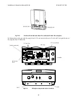
Wiring
the
inverter
The
cover
of
the
wiring
box
needs
to
be
removed
before
wiring
the
inverter.
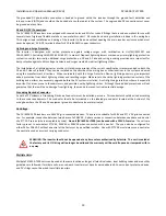
First
the
DC/AC
disconnect
switch
shall
be
turned
to
the
OFF
position
as
shown
in
the
Figure
2.3.3.
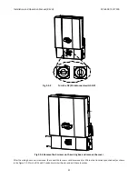
Remove
the
4
screws,
and
then
the
cover
of
the
wiring
box
shown
in
the
figure
2.3.3
and
2.3.4.


