Installation
and
Operation
Manual
(REV
H)
PVI
6500
/
PVI
7500
24
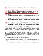
!
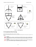
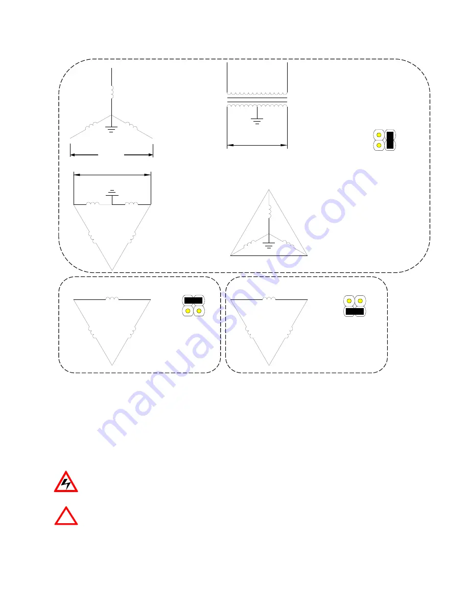
Fig
2.3.8
Utility
configurations
2.4
Connection
of
the
AC
wiring
Use
one
of
the
following
procedures
below
to
wire
the
AC
conductors.
Open
the
circuit
breaker
box,
switch
off
and
lock
out
the
circuit
breaker
box
that
will
be
used
to
connect
the
inverter
to
the
building.
WARNING!
Reconfirm
that
the
circuit
breaker
to
the
grid/utility
is
switched
OFF
and
locked
out
before
connecting
the
power
wires
from
the
breaker
to
the
inverter
AC
terminal
block.
Measure
the
absence
of
voltage
with
an
AC
voltmeter.
WARNING!
Long
wires
cause
voltage
drop.
The
acceptable
range
for
AC
voltage
drop
is
1.5%
of
nominal.
The
voltage
drop
in
excess
of
1.5%
of
nominal
AC
voltage
is
an
indication
that
larger
size
wire
should
be
used.
240
Neutral
120
120
24
0
24
0
480
48
0
48
0
277
277
277
24
0
24
0
240
20
8
20
8
208
120
120
Neutral
Neutral
120
120
240
P1
P2
Without Neutral
P1
P2
240 Delta
Without Neutral
208 Delta
P1
P2
277V / 240V / 208V
With Neutral
120 WYE
With Neutral
240/120 Split Phase
With Neutral
240 Delta
120 Stinger
With Neutral
277 WYE
With Neutral
208


