Insta
2.4
allation
and
WAR
Each
amp
prot
Use
#10
AW
.1
Conn
Connect
Connect
Connect
Connect
Tighten
t
Reconfirm
Operation
M
RNING!
h
connection
peres
(depend
tection.
WG
to
#6
AWG
nection
fo
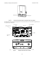
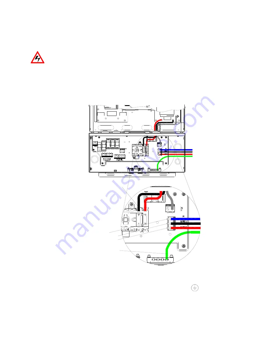
Fig
2.4
the
AC
equipm
the
white
N
w
the
L1
wire
to
the
L2
wire
to
the
screws
wit
m
that
all
con
N wire c
L2 wire
L1 wire
Equ
to
Manual
(REV
to
a
PVI
650
ding
on
inver
G,
90
C
(194
or
AC
208/
.1.1
ment
GND
wi
wire
to
the
ter
o
the
terminal
o
the
terminal
th
a
torque
of
nections
are
c
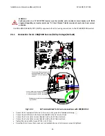
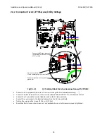
connected to N te
connected to LIN
connected to LIN
uipment ground w
ground bar
Connect the A
terminal labele
208V 240V" of
switch.
H)
00
‐
7500
inve
rter
model,
se
4
F)
copper
w
/240V
Ser
AC
Termin
re
to
the
scre
rminal
labeled
l
labeled
Line1
l
labeled
Line2
f
15.6
in
‐
lb
(1.
correct
as
des
erminal
NE 2 terminal
NE 1 terminal
wire connected
AC black wire to th
ed "BLACK FOR
f the disconnect
DCIN+
DCIN-
25
erter
must
be
ee
“AC
Circui
wire
for
all
AC
vice/Utilit
nal
Block
fo
w
on
the
grou
d
N
on
the
AC
1
on
the
AC
te
2
on
the
AC
te
.7Nm)
scribed
above
he
e
installed
w
it
Breaker”
ta
C
wiring
con
ty
Voltage
r
AC
wire
co
und
bar
labele
terminal
bloc
erminal
block.
erminal
block.
and
all
screw
J113
with
a
dedicat
able)
maximu
nections
to
t
e
(Default
onnections
ed
with
stamp
ck.
.
.
ws
are
properly
J119
ACIN_N1
PVI
6500
ted
circuit
br
um
branch
ci
the
PVI
6500
t)
with
208/2
p.
y
tightened.
0
/
PVI
7500
reaker
with
3
rcuit
over
cu
0/7500
inver
240VAC
30
‐
50
urrent
ters.


