Insta
CON
conn
Th
wire
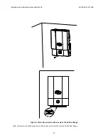
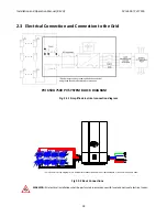
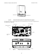
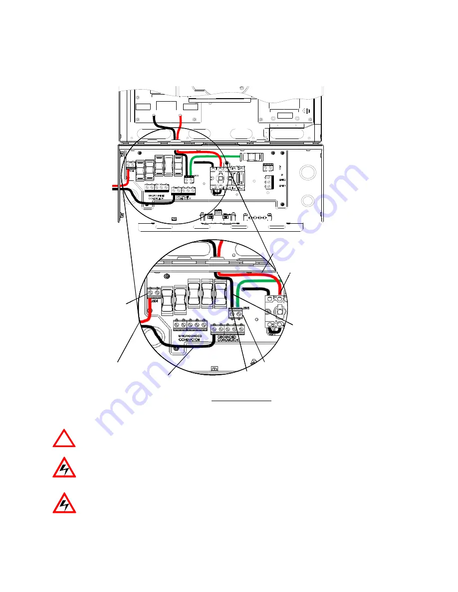
Fig
allation
and
!
DUCTOR
(WIT
nected
to
the
he
negatively
is
connected
g
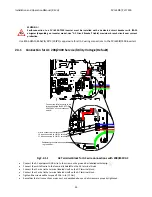
2.5.2.1
CAU
Even
pulle
WAR
Prot
(such
WAR
Haza
for
th
Operation
M
THOUT
STRIN
terminal
labe
grounded
set
to
the
termin
DC
Termin
TION!
n
though
the
er
must
be
ke
RNING!
tect
the
DC
w
h
as
sharp
cor
RNING!
rdous
voltage
he
inverter
to
Co
Connect
t
J504
Manual
(REV
NG
FUSES)”
of
led
“GROUND
tting
is
that
t
nal
labeled
“D
nal
blocks
and
internal
DC
f
ept
in
the
fuse
wires
to
the
P
rners,
edges,
e
is
still
prese
o
discharge
th
DCIN-
onnect
to
PV
‐
to
PV+
H)
f
J504
and
the
DED
CONDUCT
the
black
DC
w
D”
of
disconne
d
connections
gro
fuses
are
not
e
holder
with
PVI
6500
‐
750
or
near
cover
ent
on
the
inve
e
DC
voltage
DCIN+
29
e
negative
po
TOR”
as
show
wire
is
conne
ct
switch.
s
without
stri
ounded
syste
used,
hazard
the
(unused)
00
inverters
f
rs
where
wire
erter
after
dis
completely.
olarity
of
the
wn
in
the
figure
ected
to
the
t
ing
fuses
(usin
ems
dous
voltage
i
fuse
to
reduc
rom
any
pos
es
could
be
pi
sconnection
o
J113
Red
J505
Terminal labe
of J505
T
o
DC
input
volt
e
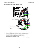
2.5.2.1.
erminal
label
ng
“J504”
byp
is
still
present
ce
the
risk
of
sible
hazards
nched
or
crus
of
all
PV
DC
in
J119
ACIN_N1
Black DC w
d DC wire
eled “C”
Terminal labele
of disconnect s
PVI
6500
age
from
the
ed
“C”
of
J50
pass
termina
t
on
the
fuse
electrical
sho
s
that
could
d
shed).
nputs.
Allow
5
wire
ed “D”
switch
0
/
PVI
7500
e
PV
string
sha
05,
and
the
re
l)
for
negativ
holders.
The
ock.
damage
the
w
5
minutes
all
be
ed
DC
vely
e
fuse
wires


