Installation
and
Operation
Manual
(REV
H)
PVI
6500
/
PVI
7500
32
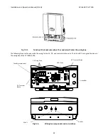
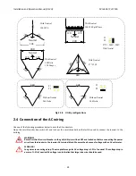
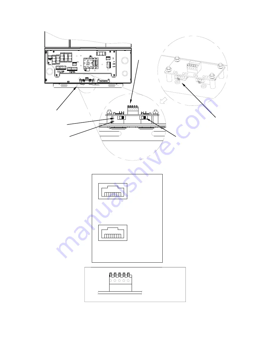
Fig
2.6.1
Positions
of
the
communication
ports
and
termination
switches
1
8
RJ45-L
Top view
Pin
1
TXD (RS232)
2
RXD (RS232)
3
Not used
4
GND
5
GND
6
Not used
7
TX A (RS485)
8
RX B (RS485)
1
8
RJ45-R
Top view
Pin
1
Factory reserved
2
Factory reserved
3
5V
4
GND
5
GND
6
5V
7
TX A (RS485)
8
RX B (RS485)
Fig
2.6.2
RJ
‐
45
Pinouts
and
Signals
Pin
1 RXD (RS232)
2 TXD (RS232)
3 GND
4 TX A (RS485)
5 TX B (RS485)
1
5
Terminal
Block
Spring
terminal
(J605)
Termination
ON/OFF
RS232
Termination
RJ45-L
RJ45-R

