Installation
and
Operation
Manual
(REV
H)
PVI
6500
/
PVI
7500
33
As
shown
in
the
Figure
2.6.2,
the
RS
‐
232
signal
pins,
TXD
and
RXD,
are
in
the
RJ45
‐
L
connector.
Therefore,
only
the
RJ45
‐
L
can
be
used
to
connect
to
when
the
RS
‐
232
interface
is
selected
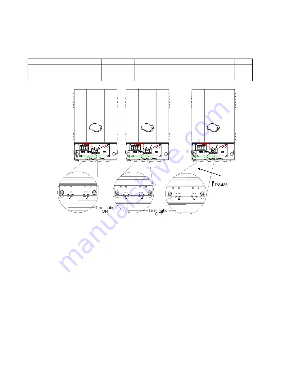
If
RS
‐
485
interface
is
selected,
both
RJ
‐
45
connectors
will
be
used
for
the
daisy
‐
chained/cascaded
RS
‐
485
connections
shown
in
the
Figure
2.6.3.
Standard
Cables
available
for
RS232
&
485
communication
for
PVI
3000
through
PVI
7500
Description
Part
Number
Typical
Use
Length
Cable,
RS485
comm.
PVI
3000
‐
7500
WIH
‐
020082
RS485
cable
for
communication
gateways
7
ft
Cable,
RS485
daisy
chain
PVI
3000
‐
7500
WIH
‐
020081
RS485
jumper
cable, for
3000
‐
7500
inverter
‐
to
‐
inverter
30
in.
Fig
2.6.3
RS
‐
485
connection
Standard
Ethernet
patch
cables
are
not
compatible
with
the
inverters,
even
though
the
inverters
use
RJ
‐
45
receptacles
and
require
CAT5e
cable,
the
pinouts
are
not
the
same
as
the
Ethernet
standard.
2.7
Communication
ID
adjustment
The
RS485
communication
ID
can
be
set
by
two
ways.
The
first
way
is
assign
the
address
value
(1
‐
254)
by
switching
each
of
the
switches
on.
The
second
way
is
setting
by
software,
where
all
of
the
switches
must
be
set
to
OFF
(0)
or
ON
(255)
in
which
case
the
ID
value
will
depend
on
an
EEPROM
parameter
which
can
be
changed
by
software
tools
via
communication
port.
When
using
SolrenView
data
monitoring
use
an
address
between
1
and
16.
SolrenView
can
automatically
detect
the
ID#
(see
SolrenView
manual).
Each
inverter
requires
a
unique
number
when
connected
to
a
single
communication
DAS.
WIH
‐
020081
RS485
Daisy
chain
To
gateway
or
computer
WIH
‐
020082

