Installation
and
Operation
Manual
(REV
H)
PVI
6500
/
PVI
7500
61
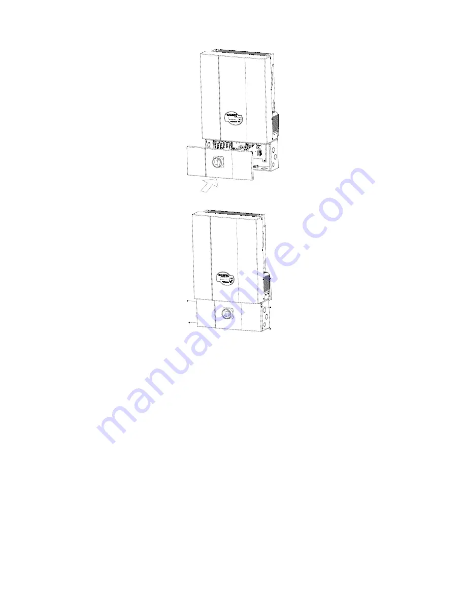
Fig
5.5.2.6
Put
the
wiring
box
cover
back
on
Fig
5.5.2.7
Fasten
the
cover
screws
then
1.
Verify
that
DC/AC
disconnect
switches
and
breakers
are
turned
off
and
locked
out.
Verify
the
absence
of
voltage
with
a
voltmeter.
2.
Remove
the
front
cover
of
the
wiring
box
by
following
the
steps
described
in
section
2.3.
3.
Remove
the
cover
plate
used
to
cover
the
through
holes
of
the
wires
and
put
it
back
to
its
original
place
as
shown
in
the
figure
5.5.2.1.
4.
Hang
the
inverter
on
the
mounting
bracket
as
shown
in
the
figure
5.5.2.2.
5.
Fasten
the
bonding
screws
with
a
torque
of
1.7Nm
(15.6
in
‐
lb)
to
the
sides
of
the
inverter
as
shown
in
the
figure
5.5.2.3.
6.
Fasten
the
attachment
nuts
with
a
torque
of
5.88
Nm
(51.96
in
‐
lb)
between
the
inverter
and
the
wiring
box
for
solid
support
and
ground
bonding
as
shown
in
the
figure
5.5.2.4.
7.
Tighten
the
nuts
with
a
torque
of
1.7Nm
(15.6
in
‐
lb)
when
performing
steps
8
and
9.
8.
For
the
AC
wire
connections,
connect
the
WHITE
AC
wire
to
the
J506
“WHITE”
terminal.
If
it
is
originally
208
/
240
V
system,
then
connect
the
RED,
BLACK
AC
wire
to
the
disconnect
switch.
If
it
is
originally
277
V
system,
then
connect
the
RED
wire
to
the
disconnect
switch
and
connect
the
BLACK
AC
wire
to
the
J506
“BLACK
for
277V”
terminal.
Please
refer
to
section
2.3
for
further
details.
9.
In
a
negatively
grounded
system,
connect
the
RED
DC
wire
to
the
disconnect
switch
and
connect
the
BLACK
DC
wire
to
the
J505
terminal
as
shown
in
the
figure
2.5.1.1.
If
the
system
is
positively
grounded,
connect
the
red
DC
wire
to
the
J505
terminal
and
connect
the
black
DC
wire
to
the
disconnect
switch
as
shown
in
the
figure
D.1.
Please
refer
to
the
section
2.3.2
for
further
details.
10.
Put
the
covers
of
the
wiring
box
back
as
shown
in
the
figure
5.4.3.2.6.
Fasten
the
screws
as
shown
in
the
figure
5.5.2.7.
11.
Unlock
Turn
ON
the
DC/AC
disconnect
switch
and
breakers
while
wearing
personal
protective
equipment.


