Insta
The
integ
DC
The
from
from
Th
is
co
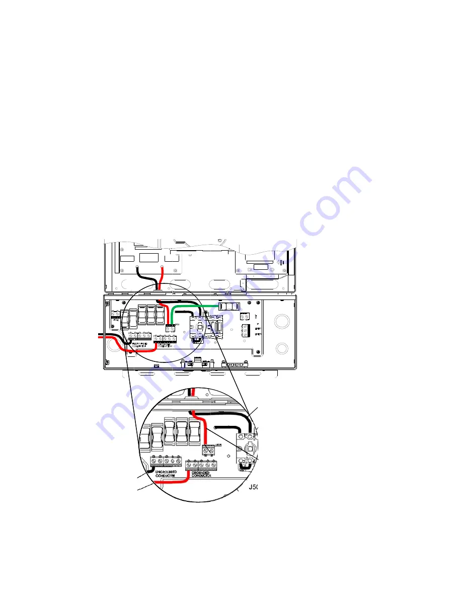
Fig
D
allation
and
C
P
C
PVI
6500
‐
750
grated
discon
wiring
fo
PVI
6500/750
m
the
PV
string
m
the
PV
string
he
positively
g
nnected
to
th
D.1
Operation
M
D
Connect to
PV-
Connect to
0
inverter
sup
nect
must
bre
Ensure
that
t
Disconnect
th
Disconnect
th
Connect
the
r
Connect
the
b
Tighten
the
s
r
Positive
00
inverter
su
g
shall
be
con
g
shall
be
conn
grounded
sett
he
terminal
lab
Positively
G
Manual
(REV
DCIN+
DCIN-
pports
positive
eak
the
ungro
he
inverter
is
he
black
DC
w
he
red
DC
wire
red
DC
wire
to
black
DC
wire
et
screws
to
a
ly
Ground
upports
PV
po
nected
to
the
nected
to
the
ting
is
that
the
beled
“D”
of
d
Grounded
S
H)
ely
grounded
unded,
negat
off
and
de
‐
en
wire
connected
e
connected
t
o
terminal
“C”
to
terminal
“
a
torque
of
1.7
ded
System
ositively
grou
e
GROUNDED
UNGROUNDE
e
red
DC
wire
disconnect
sw
Setting
and
72
J1
Te
“C”
arrays.
To
con
ive
conductor
nergized
from
d
to
terminal
“
to
terminal
“D
”
on
terminal
“D”
on
the
disc
7Nm
(15.6
in
‐
ms
for
use
nded
arrays.
CONDUCTOR
ED
CONDUCTO
is
connected
witch.
DC
conduc
13
J119
ACIN_N1
Red DC
Black DC
J50
erminal labeled
” of J505
Termina
“D” of dis
nfigure
the
in
r.
both
AC
and
“C”
on
termin
D”
on
the
disco
block
J505.
connect
switc
‐
lb.))
e
with
Inte
In
this
case
t
terminal
and
OR
terminal
a
to
the
termin
ctor
connec
wire
C
d
al labeled
sconnect
verter
for
pos
DC
sides.
nal
block.
onnect
switch
ch.
egrated
S
the
positive
p
the
negative
as
shown
in
th
nal
labeled
“C
tions
(using
PVI
6500
sitive
grounde
h.
String
Fuse
polarity
of
the
polarity
of
th
he
figure
D.1.
”
of
J505,
and
g
PV
string
0
/
PVI
7500
ed
arrays,
the
es
e
DC
input
vo
he
DC
input
vo
d
the
black
DC
fuses)
oltage
oltage
C
wire


