background image


FOR 

PVI


3800-7600TL 

 11 

Rapid Shutdown Combiner Installation and Operation Guide (Rev B) 

DOCR-070566-B                                            


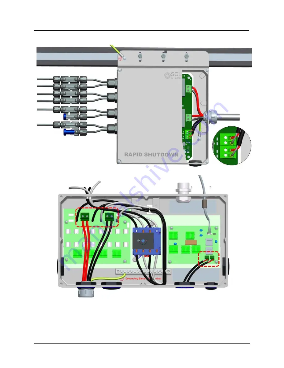
Connect DC wire to the DC wiring board  

And connect 5V signal wire to the AC wiring board of Solectria single-phase PV 

inverter 

Note: Redundant wiring is shown for 5V signal wire 

Fig.6 Terminal Wiring Diagram of Solectria RSD Combiner 

Summary of Contents for Rapid Shutdown

Page 1: ...RAPID SHUTDOWN COMBINER Installation and Operation Guide Revision B 2017 Yaskawa Solectria Solar ...

Page 2: ...ous situation which if not avoided could result in death or serious injury CAUTION CAUTION indicates a hazardous situation which if not avoided could result in minor or moderate injury NOTICE NOTICE indicates a situation that can result in property damage if not avoided HIGH VOLTAGE WARNING Indicates hazardous high voltages are present which if not avoided will result in death or serious injury On...

Page 3: ...vent devenir chaud 2 Rapid Shutdown Combiner The Solectria RSD Combiner provides an automatic disconnect of 600 VDC residential or small commercial PV array systems fully compliant with the Rapid Shutdown requirements of NEC 2014 article 690 12 when installed appropriately It is compatible with Solectria s single phase residential inverters PVI 3800TL PVI 5200TL PVI 6600TL and PVI 7600TL Solectria...

Page 4: ...ones 1 string per RSD input Examples 2 3 strings of 260W module 12 modules per string and a PVI 7600TL using both MPPT zones 1 string on one side and 2 strings on the other Fig 1 Connection Diagram of Solectria RSD Combiner Always check with the local inspector on wire routing SOLECTRIA RAPID SHUTDOWN COMBINER ON ROOF WITHIN 10 OF PV SOLECTRIA RAPID SHUTDOWN COMBINER ON ROOF WITHIN 10 OF PV ...

Page 5: ...contactors to open inside the RSD Combiner ensuring there is no high voltage DC between the inverter and the RSD Combiner The PV system with rapid shutdown ability shall be properly labeled according to NEC 690 56 C The sign label should be right at the service entrance and match the sample below text and color scheme PHOTOVOLTAIC SYSTEM EQUIPPED WITH RAPID SHUTDOWN Sealing Cap PV Connector PV Wir...

Page 6: ...ENERAL DATA Enclosure size L x W x D 12 4 x 10 x 2 2 inches 316 x 255 x 55 mm Weight 6 6 lbs 3 0 kg DC input connectors Amphenol Helios H4 PV connector DC output connectors Screw terminal blocks Operating temperature 40 158 F 40 70 C Storage temperature 40 185 F 40 85 C Humidity 0 100 non condensing Max operating altitude 2000 m above sea level Warranty 10 years STANDARD COMPLIANCE Enclosure prote...

Page 7: ... PV string before completing all installation and DC output connection Once connected to PV string the RSD Combiner will wake up immediately Danger High Voltage Risk of electric shock WARNING Installation and commissioning must be performed by a licensed electrician in accordance with local state and National Electrical Code ANSI NFPA 70 requirements In Canada the installation and wiring methods u...

Page 8: ... pollution degree II certification the RSD Combiner must not be exposed to heavy soiling CAUTION Unused connectors and holes must be covered with sealing connectors and plugs 5 1 Mounting the RSD combiner Fig 4 Mounting SOLECTRIA RSD Combiner Mount the RSD Combiner under the PV module away from rain and sun Do not mount the RSD Combiner in a position that allows long term exposure to direct sunlig...

Page 9: ...the RSD combiner is installed outdoors 5 2 Opening the cover of RSD combiner Remove the 4 M4 cover screws with a T20 Torx screw driver To replace the cover screws use a torque of 16 in lbs 1 8 Nm WARNING Ensure no live voltages are present on PV input and output circuit before RSD Combiner installation 5 3 Grounding The Solectria RSD Combiner has an external threaded grounding point for bonding to...

Page 10: ...nnections NOTICE All screw terminals of the DC outputs accept solid or stranded 12 6 AWG copper wire only Stranded wire is recommended A 1 8 3 5 mm flat head bit is recommended for tightening screw terminals to a torque of 10 5 in lbs 1 2 Nm CAUTION The rapid shutdown signal wire may be routed together with the DC output cables in the same conduit but all the cables shall be listed and rated 600 V...

Page 11: ...peration Guide Rev B DOCR 070566 B Connect DC wire to the DC wiring board And connect 5V signal wire to the AC wiring board of Solectria single phase PV inverter Note Redundant wiring is shown for 5V signal wire Fig 6 Terminal Wiring Diagram of Solectria RSD Combiner ...

Page 12: ...e damage to the equipment 5 7 PV string fuses Replacement NOTICE The maximum acceptable string fuse for the RSD Combiner is 20A KLKD 20 Use of larger fuses will void the warranty Always replace the string fuse with the same rating and UL CSA listed PV fuse 6 Product Warranty and RMA Policy The current warranty and RMA statement for the product is available online at http www solectria com support ...

Page 13: ...pvi 3800 7600tl Appendix B String Sizing Tool https solectria com support string sizing tool Appendix C Contact Information Yaskawa Solectria Solar 360 Merrimack Street Building 9 Floor 2 Lawrence Massachusetts 01843 USA Tel 978 683 9700 Fax 978 683 9702 Sales General Info inverters solectria com Technical Support Service 978 683 9700 x2 Website www solectria com Appendix D Authorized Distributors...

Page 14: ...FOR PVI 3800 7600TL 14 Rapid Shutdown Combiner Installation and Operation Guide Rev B DOCR 070566 B Appendix E UL1741 IEEE1547 Certification Letter ...

Page 15: ...FOR PVI 3800 7600TL 15 Rapid Shutdown Combiner Installation and Operation Guide Rev B DOCR 070566 B ...

Reviews: