1–4
Preparing for the Installation
•
CPU and I/O assembly controls and indicators, Section 1.4.3
•
Memory modules, Section 1.4.4
•
Primary breakout module, Section 1.4.5
•
Secondary breakout module, Section 1.4.6
•
PMC I/O companion card, Section 1.4.7
1.4.1 CPU Module
The CPU module is the compute engine of Alpha VME 5/352 and 5/480 SBCs.
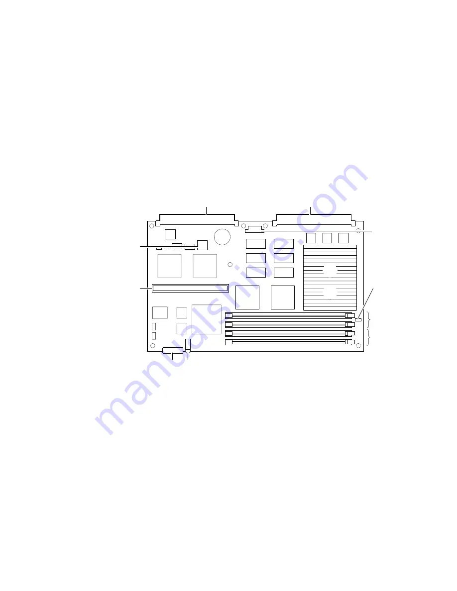
Figure 1–1 shows the layout and primary components.
Figure 1–1 CPU Module Layout
The numeric callouts in the figure identify the following key components:
1
P1 VMEbus connector
2
P2 VMEbus connector
3
64-bit PCI connector (not used)
4
J11 bus grant pass-through jumper
5
Connectors for memory DIMMs 2 and 3
6
Connectors for memory DIMMs 0 and 1
7
Power and VME slave activity/watchdog timeout LED
8
Status display
9
I/O module connector
10
SROM
ML013781
5
9
7
8
3
1
2
10
6
4


