Preparing for the Installation
1–15
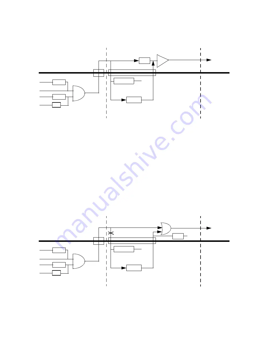
Figure 1–9 Active Buffer Backplane
Backplanes that use OR Devices
For active backplanes that use the OR gate circuit configuration shown in
Figure 1–10, you must:
–
Install the J11 bus grant pass-through jumper.
–
On the backplane, disconnect the BG_IN_L<3:0> signals from the back-
plane to the I/O module.
In this circuit configuration, the CPU module drives the BG_IN_L<3:0>
signal low, enabling the backplane OR gate. The VIC 64 chip on the I/O
module in slot 2 needs this signal input to be high. By disconnecting the
BG_IN_L<3:0> signals from the backplane to the I/O module, you cause
the passive pullups on the I/O module to pull the VIC 64 BG_IN_L<3:0>
signals high.
Figure 1–10 Active OR Backplane
AND
4.75 K
4.75 K
VDD
BG_IN_L<3:0>
VDD
GND
BG_OUT_L<3:0>
BG_PASS_THRU_H
CPU Module
Slot 1
BG_IN_L<3:0>
8.2 K
BG_OUT_L<3:0>
4.7 or 33 K
VDD
VIC 64
BG_IN_L<3:0>
Slot 2
Slot 3
I/O Module
BG_OUT_L<3:0>
J11
AND
4.75 K
4.75 K
VDD
BG_IN_L<3:0>
VDD
GND
BG_OUT_L<3:0>
BG_PASS_THRU_H
CPU Module
Slot 1
BG_IN_L<3:0>
80 K
BG_OUT_L<3:0>
4.7 or 33 K
VDD
VIC 64
BG_IN_L<3:0>
Slot 2
Slot 3
I/O Module
BG_OUT_L<3:0>
J11
OR
GND
Disconnect here


