Installing the SBC
2–3
2.2 Setting Configuration Switches on the I/O Module
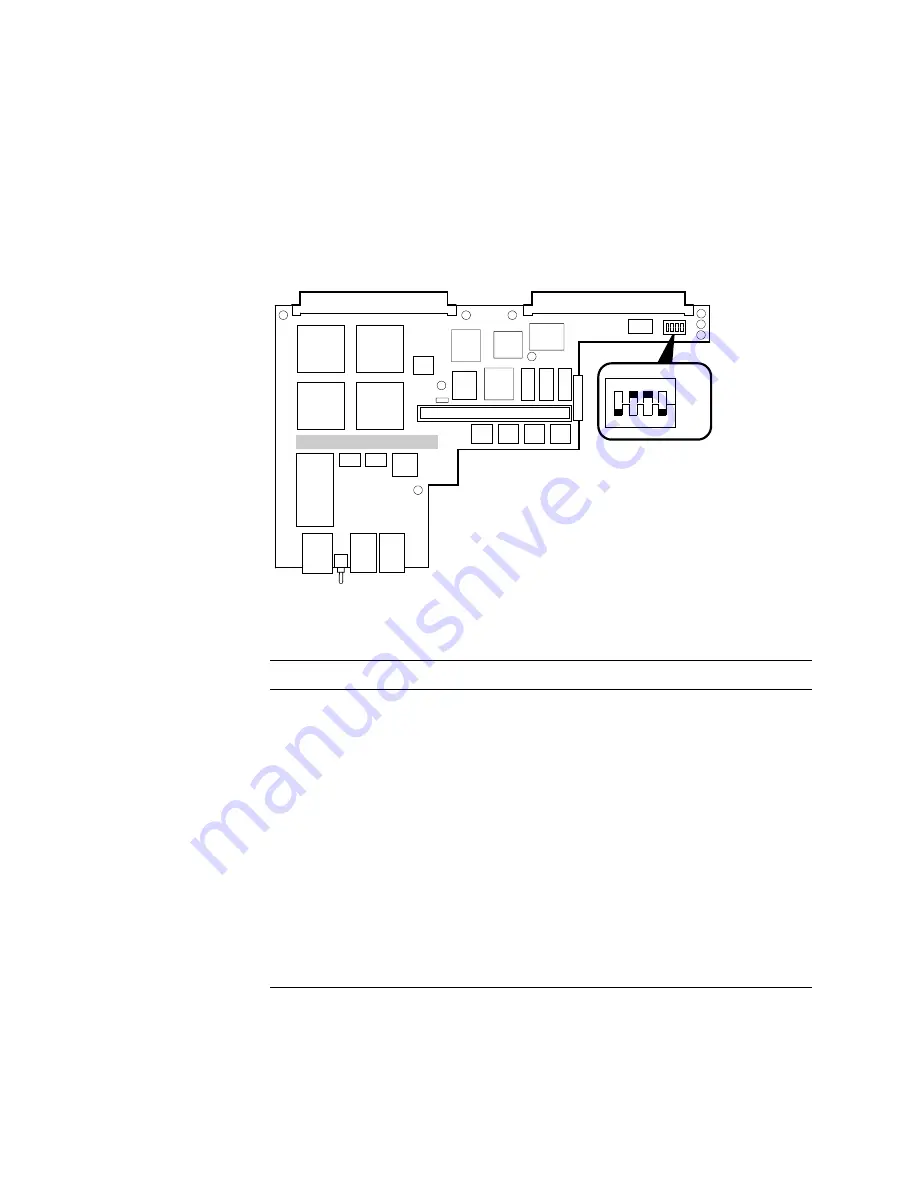
The first step to installing an Alpha VME 5/352 or 5/480 SBC is to set the config-
uration switches on the I/O module. Figure 2–2 shows the location of the configu-
ration switches. Use the information in Tables 2–1 through 2–3 to set the switches
based on your system needs.
Figure 2–2 Setting I/O Module Configuration Switches
.
Table 2–1 I/O Module Configuration Switches
Switch
Setting
Function
1
Closed
Su5 V from the 5 V Standby signal to the time-
of-year (TOY) clock and the nonvolatile random-access memory
(NVRAM) to supplement the internal battery when the SBC’s
power is turned off.
Open
Does not supply power from the 5 V Standby signal.
The internal battery lasts for about 10 years with the SBC’s
power turned off.
2
Closed
Enables the writing of flash ROMs under program control.
Open
Disables the writing of flash ROMs.
3
Closed
Enables the VMEbus Reset signal for resetting the SBC.
Open
Disables the VMEbus Reset signal.
4
Closed
The SBC is the VMEbus system controller.
Open
The SBC is not the VMEbus system controller.
ML013788
ON
OFF
OPEN
4
3
2
1


