Installing the SBC
2–7
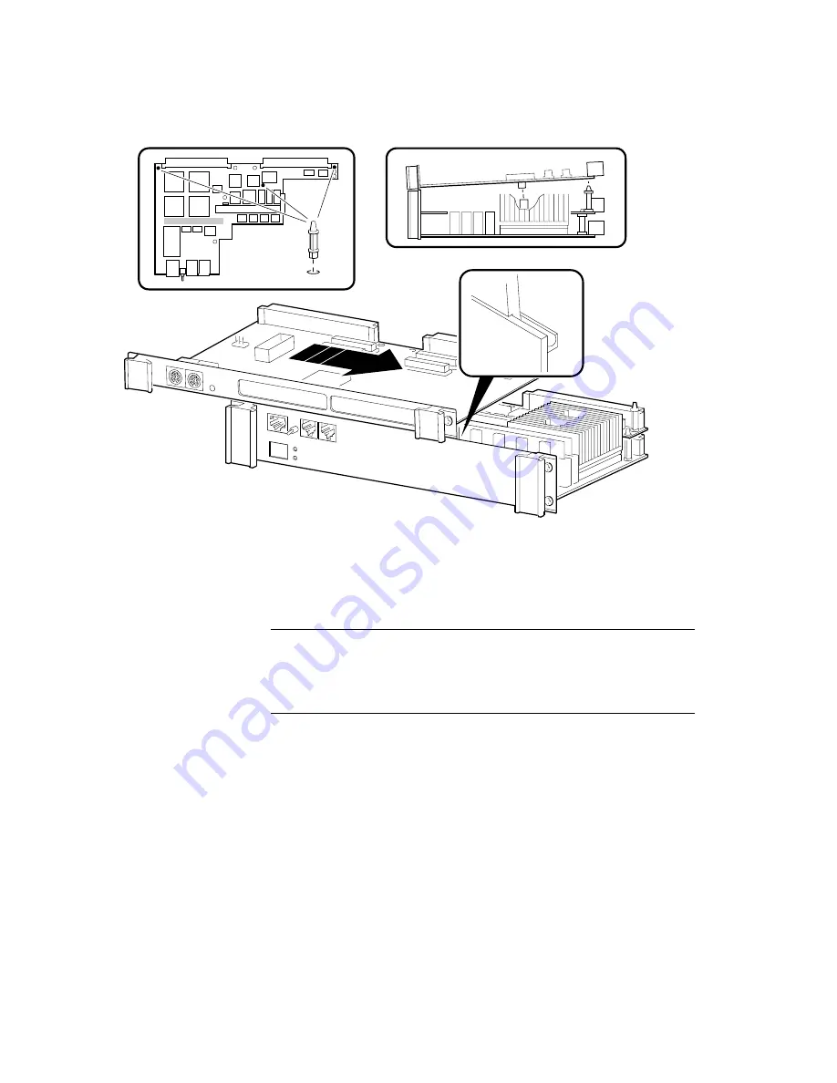
Figure 2–5 Connecting the PMC I/O Companion Card to the I/O Module
b.
Raise the PMC I/O companion card at a slight angle from the I/O module
and slide the connecting edges together until the connector on the bottom
of the PMC I/O companion card is aligned with its mating connector on
the top side of the I/O module as shown in Figure 2–5.
Caution
You must align the connector precisely. If the alignment is not precise,
the force required for normal connector mating is sufficient to damage the
connector housing and pins.
c.
Carefully press down on both sides of the I/O module connector, causing
the I/O module and PMC I/O companion card connectors to mate and the
standoffs to anchor as shown in Figure 2–5.
2.5 Installing the CPU and I/O Modules in the VME Chassis
Once you have the CPU, I/O, and PMC I/O companion card (if applicable) mod-
ules connected, you must install the assembled components in a VME chassis.
Figure 2–6 shows how to install a 2-slot assembly consisting of the CPU and I/O
modules. Figure 2–7 shows how to install a 3-slot assembly that includes the
CPU, I/O, and PMC I/O companion card modules.
ML013265


