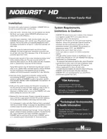
Begin by filling the solar tank with water. Do this by opening the cold-water isolation ball valve to the solar tank. When the tank
is filled, inspect all threaded fittings and solder joints for leaks.
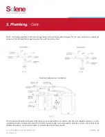
Fill and pressurize the solar collector loop with water. Begin by connecting a washing machine hose to the upper charge valve
and fill the collector loop with water. The isolation ball valve remains closed at this point. While the hose is still connected to
the upper charge valve and the water is running, open the lower purge/drain valve and let the water run out until it is free
of impurities or debris that might have entered the piping as the components were plumbed. Run the water long enough to
eliminate any air bubbles that may be trapped in the system
Close the lower purge/drain valve. The collector loop now has been subjected to city pressure and the pressure gauge should
read somewhere in the range of 50 – 75 psi in most cases. Make a final inspection of the collector plumbing connections to
ensure that there are no leaks anywhere in the collector loop piping.
1.
2.
3.
8. Electrical & Wiring Requirements.
9. Thermometers.
(Optional)
10. Charging the System.
INSTALLATION MANUAL SOLENE
®
HOT WATER SYSTEMS
©
2014 UMA Solar
A properly licensed contractor must make the 230-volt electrical connection to the water heater or solar storage tank and the
electronic time switch (Optional). If your solar contractor is not allowed by law to make these connections consult a licensed
electrician. NEVER ACTIVATE THE CIRCUIT BREAKER CONTROLLING THE ELECTRICAL HEATING ELEMENT UNTIL THE SOLAR STORAGE
TANK IS COMPLETELY FILLED WITH WATER. This will prevent “dry firing” of the heating element. The electrical heating element will be
destroyed almost instantaneously if not completely submerged in water when activated. Make sure the water heater circuit breaker
is off until the solar storage tank is completely filled.
We recommend the use of a 115-volt differential control with a factory installed six-foot line cord. The installation requires one 115-
volt outlet to be installed near the solar storage tank. Plug the control into the outlet. The circulation pump line cord is plugged into
the receptacle on the side of the controller. A 230-volt control and circulation pump may be substituted, but troubleshooting the
components in the future becomes more difficult.
The specified differential thermostat is the Goldline model GL-30-LCO or Steca model TR0301-US.
Locate two thermometers; one at the supply line and one on the return line of the solar loop so that the temperature rise across the
collector can be determined.
Once the components are plumbed you are ready to fill the solar storage tank with water and to charge the collector loop with a
mixture of heat transfer fluid (HTF) and distilled or de-ionized water. The use of regular tap water as a mixing agent is prohibited.
Proceed as follows:
ELECTRICAL & WIRING REQUIREMENTS | THERMOMETERS | CHARGING THE SYSTEM.
-
12


