11
6.6. ELECTRICAL CONNECTION
The CAD-COMPACT ECOWATT range are supplied without a complete operating control integrated in the
unit. The electrical components included in the unit are supplied wired in an electrical cabinet located
in one side of the unit. To access the electrical terminal block and conveniently make the electrical con-
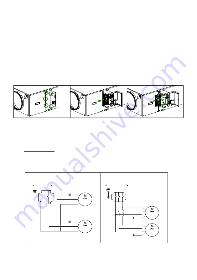
nection of the accessories it is advisable to remove the connection board, follow the following sequence:
1. Loosen the 5 screws that are distributed by the cover of the electrical cabinet (Fig. 1)
2. Open the cover and pull the metal plate on which the electrical terminals are located until it is outside
the cabinet (Fig. 2).
3. The electrical cabinet has a PG connector for the electrical power cable. Further of this, in a bag that
is supplied inside the unit, there are 3 more connectors that can be used to route the control wiring
to the control accessories or the control panel of the building. Pass the necessary wiring through the
connectors.
4. Make the electrical connection to the control board and put it back inside the electrical cabinet, ma-
king it slide through the existing guides (Fig. 3).
)LJ
)LJ
)LJ
6.6.1. Wiring diagram
CAD-COMPACT models 500 to 3200 have plug-fans with EC motors 230V supply voltage, while the
CAD-COMPACT 4500 model have fans with a three-phase motor.
The electrical wiring consists of two phases: the power supply of the fans and the control wire.
Fans power wiring
The two fans are wired to the switch located on the lid of the electrical cabinet. To power the fans,
wire the power line to the terminals of the switch.
dϭ
E
E
>ϭ
^hWW>z
&E
ydZd
&E
(/(&75,&$/
32:(56833/<
ϮϯϬͬ/ͬϱϬͲϲϬ,nj
'E
%/8(
%52:1
%/8(
'E
%52:1
'E
>ϭ
>ϯ
>Ϯ
(/(&75,&$/
32:(56833/<
ϰϬϬͬϯͬϱϬͲϲϬ,nj
%52:1
%/$&.
*5(<
^hWW>z
&E
ydZd
&E
'E
%52:1
*5(<
%/$&.
'E
KDWdϱϬϬdKϯϮϬϬDK>^
&$'&203$&702'(/


