19
7. INSPECTION, MAINTENANCE AND CLEANING
7.1. FILTERS REPLACEMENT
The registers ubication for fi lters maintenance depends on the model and version. The exact ubication
of the fi lters is identifi ed by a label in the profi le that indicates the type of fi lter and its characteristics.
FALLING OBJECTS
By loosening the screws that hold the panels, they will be released. In units installed in
ceiling, pay special attention to this operation to prevent the fall of a panel. During the
maintenance signaling the area below the heat recovery unit and prevent personnel ac-
cess to it.
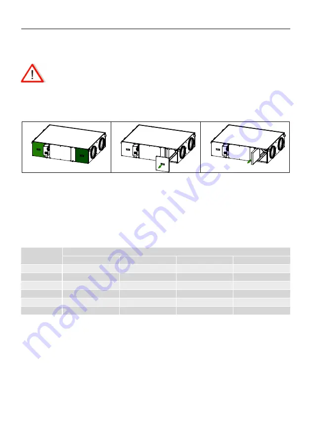
Access to fi lters is done by removing the two registration panels located on the side of the heat recovery
unit. To replace the fi lters, follow the following sequence:
Fig.3
Fig.2
Fig.1
1. Access to the fi lters is done by removing the two existing side panels on the side where the electrical
cabinet is located (Fig.1).
2. Remove the 4 screws that fi x the fi lter access panel. Hold the panel preventing it from falling when
loosening the last screw. (Fig 2).
3. Pull the dirty fi lter outwards, sliding it on the existing guide.
In the process of assembling the new fi lter, follow the reverse order, paying attention to the arrow that
defi nes the direction of the air that you will fi nd in the new S&P fi lter.
Filters spare parts table
Model
Accessory fi lters and spare parts for CAD COMPACT*
G4
M5
F7
F9
CAD COMPACT 500
AFR-CAD COMPACT 500 G4
AFR-CAD COMPACT 500 M5
AFR-CAD COMPACT 500 F7
AFR-CAD COMPACT 500 F9
CAD COMPACT 900
AFR-CAD COMPACT 900 G4
AFR-CAD COMPACT 900 M5
AFR-CAD COMPACT 900 F7
AFR-CAD COMPACT 900 F9
CAD COMPACT 1300
AFR-CAD COMPACT 1300 G4
AFR-CAD COMPACT 1300 M5
AFR-CAD COMPACT 1300 F7
AFR-CAD COMPACT 1300 F9
CAD COMPACT 1800
AFR-CAD COMPACT 1800 G4
AFR-CAD COMPACT 1800 M5
AFR-CAD COMPACT 1800 F7
AFR-CAD COMPACT 1800 F9
CAD COMPACT 3200
AFR-CAD COMPACT 3200 G4
AFR-CAD COMPACT 3200 M5
AFR-CAD COMPACT 3200 F7
AFR-CAD COMPACT 3200 F9
CAD COMPACT 4500
AFR-CAD COMPACT 4500 G4
AFR-CAD COMPACT 4500 M5
AFR-CAD COMPACT 4500 F7
AFR-CAD COMPACT 4500 F9
* In serial, the units are supplied with F7 as standard and M5 as extraction. All models allow the assembly of a second fi lter
inside, obtaining, among others, the following combinations: F7 + F9, M5 + F7 or G4 + F7.
7.2. ADDITIONAL FILTER INSTALLATION
The heat recovery is supplied with mounted fi lters.
Low pressure F7 fi lter for supply air and M5 for extract air.
Inside the heat recovery unit there is a specifi c rail for mounting a second additional fi lter (supplied as
an accessory).


