20
7.3. HEAT EXCHANGER
To perform the heat exchanger cleaning it is necessary to remove it from the unit. The disassembly can
be easily done from the lateral panel:
Core disassembly sequence per side
To disassemble of the heat exchanger follow the following sequence:
• Loosen the screws that hold the side panel. Before releasing the panel, ensure that it is well suppor-
ted by the operator, preventing it from falling (Fig. 1).
• Remove the bypass assembly, releasing its electrical connector (Fig. 2).
• Pull the heat exchanger until it is completely removed from the equipment (Fig. 3).
Fig.1
3
.
g
i
F
2
.
g
i
F
7.4. FANS
It is not necessary to access the fan to carry out maintenance tasks, nor to carry out the electrical
connection since both fans are wired to the electrical cabinet. However, it is necessary to leave enough
space around the equipment so that it is possible to access the fans in the event of their failure. Do not
install the heat exchanger against a wall or an obstacle that prevents access to the fans.
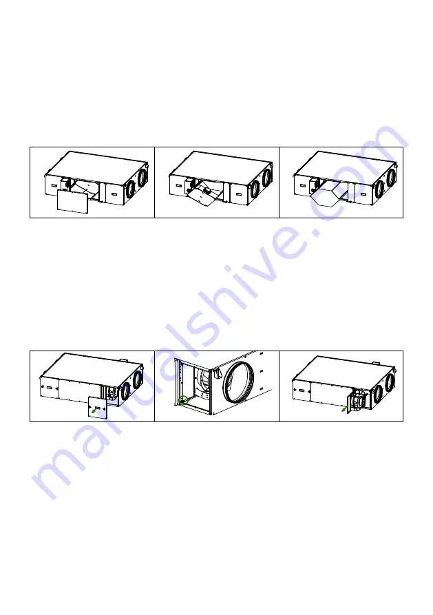
In case of need to replace the fan, follow the following sequence:
• Remove the access panel for the affected fan (Fig. 1).
• Release the screws that lock the metal plate on which the fan is mounted (Fig. 2).
• Pull out the plate and once outside, remove the fan and proceed to replace it (Fig. 3).
)LJ
)LJ
)LJ
7.5. CONDENSATION DRAINPIPE
Inspect the drainpipe regularly and make sure it is not blocked, if this is the case, remove the obstruc-
tion.
Check that the drain pipe was done according to the indication included in the point CONNECTIONS of
this manual.
The siphon should always be full of water. Check its level periodically, refi lling it if necessary. An empty
siphon can cause the condensate tray to overfl ow and water leak through the equipment enclosure.


